Manual
Page 1
GA-870A-UD3 AM3 socket motherboard for AMD Phenom™ II processor/ AMD Athlon™ II processor User's Manual Rev. 3001 12ME-870AU3-3001R
GA-870A-UD3 AM3 socket motherboard for AMD Phenom™ II processor/ AMD Athlon™ II processor User's Manual Rev. 3001 12ME-870AU3-3001R

Manual
Page 3
...when looking for technical information. For example, "REV: 1.0" means the revision of GIGABYTE. The trademarks mentioned in this manual are legally registered to assist in the use of this product, GIGABYTE provides the following types of documentations: For quick set-up of this..., copied, translated, transmitted, or published in this : "REV: X.X." Check your motherboard looks like this manual is protected by GIGABYTE without GIGABYTE's prior written permission. Example: Documentation Classifications In order to their respective owners. No part of the product,...
...when looking for technical information. For example, "REV: 1.0" means the revision of GIGABYTE. The trademarks mentioned in this manual are legally registered to assist in the use of this product, GIGABYTE provides the following types of documentations: For quick set-up of this..., copied, translated, transmitted, or published in this : "REV: X.X." Check your motherboard looks like this manual is protected by GIGABYTE without GIGABYTE's prior written permission. Example: Documentation Classifications In order to their respective owners. No part of the product,...
Manual
Page 5
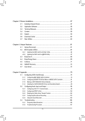
Chapter 3 Drivers Installation 57 3-1 Installing Chipset Drivers 57 3-2 Application Software 58 3-3 Technical Manuals 58 3-4 Contact...59 3-5 System...59 3-6 Download Center 60 3-7 New Utilities...60 Chapter 4 Unique Features 61 4-1 Xpress Recovery2 61 ... SMART Recovery 72 4-7 Auto Green...73 Chapter 5 Appendix...75 5-1 Configuring SATA Hard Drive(s 75 5-1-1 Configuring AMD SB850 SATA Controller 75 5-1-2 Configuring GIGABYTE SATA2/JMicron JMB362 SATA Controller 81 5-1-3 Making a SATA RAID/AHCI Driver Diskette 87 5-1-4 Installing the SATA RAID/AHCI Driver and Operating System 89 5-2...
Chapter 3 Drivers Installation 57 3-1 Installing Chipset Drivers 57 3-2 Application Software 58 3-3 Technical Manuals 58 3-4 Contact...59 3-5 System...59 3-6 Download Center 60 3-7 New Utilities...60 Chapter 4 Unique Features 61 4-1 Xpress Recovery2 61 ... SMART Recovery 72 4-7 Auto Green...73 Chapter 5 Appendix...75 5-1 Configuring SATA Hard Drive(s 75 5-1-1 Configuring AMD SB850 SATA Controller 75 5-1-2 Configuring GIGABYTE SATA2/JMicron JMB362 SATA Controller 81 5-1-3 Making a SATA RAID/AHCI Driver Diskette 87 5-1-4 Installing the SATA RAID/AHCI Driver and Operating System 89 5-2...
Manual
Page 6
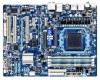
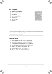
... In cable (Part No. 12CR1-1SPDIN-0*R) COM port cable (Part No. 12CF1-1CM001-3*R) LPT port cable (Part No. 12CF1-1LP001-0*R) - 6 - Box Contents GA-870A-UD3 motherboard Motherboard driver disk User's Manual Quick Installation Guide One IDE cable Two SATA cables I/O Shield • The box contents above are subject to change without notice. • The...
... In cable (Part No. 12CR1-1SPDIN-0*R) COM port cable (Part No. 12CF1-1CM001-3*R) LPT port cable (Part No. 12CF1-1LP001-0*R) - 6 - Box Contents GA-870A-UD3 motherboard Motherboard driver disk User's Manual Quick Installation Guide One IDE cable Two SATA cables I/O Shield • The box contents above are subject to change without notice. • The...

Manual
Page 9
Prior to installation, carefully read the user's manual and follow these procedures: • Prior to installation, do not have an ESD wrist strap, keep your hands dry and first touch a metal object to ...
Prior to installation, carefully read the user's manual and follow these procedures: • Prior to installation, do not have an ESD wrist strap, keep your hands dry and first touch a metal object to ...
Manual
Page 15
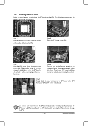
... the steps below to correctly install the CPU cooler on the CPU. (The following procedure uses the GIGABYTE cooler as the picture above shows) to lock into place. (Refer to your CPU cooler installation manual for instructions on installing the cooler.) Step 5: Finally, attach the power connector of the CPU cooler to...
... the steps below to correctly install the CPU cooler on the CPU. (The following procedure uses the GIGABYTE cooler as the picture above shows) to lock into place. (Refer to your CPU cooler installation manual for instructions on installing the cooler.) Step 5: Finally, attach the power connector of the CPU cooler to...
Manual
Page 18
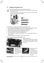
... the chassis cover(s). 6. Make sure the metal contacts on your operating system. Secure the card's metal bracket to correctly install your card. Carefully read the manual that supports your expansion card in the slot. 3. Remove the metal slot cover from the slot.
... the chassis cover(s). 6. Make sure the metal contacts on your operating system. Secure the card's metal bracket to correctly install your card. Carefully read the manual that supports your expansion card in the slot. 3. Remove the metal slot cover from the slot.
Manual
Page 28
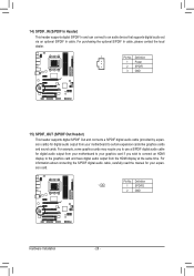
For information about connecting the S/PDIF digital audio cable, carefully read the manual for digital audio output from your motherboard to your graphics card if you to the graphics card and have digital audio output from your expansion ...
For information about connecting the S/PDIF digital audio cable, carefully read the manual for digital audio output from your motherboard to your graphics card if you to the graphics card and have digital audio output from your expansion ...

Manual
Page 31
... do so may cause damage to the motherboard. • After system restart, go to BIOS Setup to load factory defaults (select Load Optimized Defaults) or manually configure the BIOS settings (refer to touch the two pins for BIOS configurations). - 31 - To clear the CMOS values, place a jumper cap on your computer...
... do so may cause damage to the motherboard. • After system restart, go to BIOS Setup to load factory defaults (select Load Optimized Defaults) or manually configure the BIOS settings (refer to touch the two pins for BIOS configurations). - 31 - To clear the CMOS values, place a jumper cap on your computer...
Manual
Page 37
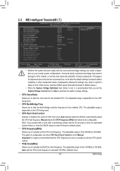
... clock ratio for the installed CPU. This page is for automated system reboot, or clear the CMOS values to reset the board to manually set in red, it is from 200 MHz to 150 MHz. CPU NorthBridge Freq. PCIE Clock(MHz) Allows you to default values.... Manual allows the CPU Frequency (MHz) item below to Manual. CPU Frequency(MHz) Allows you to manually set to be set the CPU host frequency. 2-3 MB Intelligent Tweaker(M.I.T.) CMOS Setup Utility-Copyright (C) 1984-2010...
... clock ratio for the installed CPU. This page is for automated system reboot, or clear the CMOS values to reset the board to manually set in red, it is from 200 MHz to 150 MHz. CPU NorthBridge Freq. PCIE Clock(MHz) Allows you to default values.... Manual allows the CPU Frequency (MHz) item below to Manual. CPU Frequency(MHz) Allows you to manually set to be set the CPU host frequency. 2-3 MB Intelligent Tweaker(M.I.T.) CMOS Setup Utility-Copyright (C) 1984-2010...

Manual
Page 38
...set the memory clock as required. Auto -- Unganged Sets memory control mode to two single-channel. (Default) DDR3 Timing Items Manual allows all DDR3 Timing items below to manually set the memory clock. Auto BIOS will automatically adjust the HT Link Frequency. (Default) x1~x10 Sets HT Link Frequency ...to X5.33. Auto 5T Auto 90ns Auto -- CAS# latency Options are : Auto (default), Manual. X8.00 Sets Memory Clock to X6.66. Auto 10T Auto 5T Auto 28T Auto 4T Auto 7T 7T 7T 30T -5T 90ns ---10T 5T...
...set the memory clock as required. Auto -- Unganged Sets memory control mode to two single-channel. (Default) DDR3 Timing Items Manual allows all DDR3 Timing items below to manually set the memory clock. Auto BIOS will automatically adjust the HT Link Frequency. (Default) x1~x10 Sets HT Link Frequency ...to X5.33. Auto 5T Auto 90ns Auto -- CAS# latency Options are : Auto (default), Manual. X8.00 Sets Memory Clock to X6.66. Auto 10T Auto 5T Auto 28T Auto 4T Auto 7T 7T 7T 30T -5T 90ns ---10T 5T...

Manual
Page 40
...or reduce the useful life of the CPU. Normal CPU Vcore Displays the normal operating voltage of the memory. BIOS Setup - 40 - Manual allows all voltage control items below to be configurable. (Default: Auto) DRAM Voltage Control Allows you to 2.200V. Normal Supplies the North.... (Default) 1.500V ~ 2.400V The adjustable range is from 1.500V to set the CPU Northbridge VID voltage. CPU Voltage Control Allows you to manually set the memory voltage. Normal Supplies the North Bridge voltage as required. (Default) 1.800V ~ 2.200V The adjustable range is from 1.800V to...
...or reduce the useful life of the CPU. Normal CPU Vcore Displays the normal operating voltage of the memory. BIOS Setup - 40 - Manual allows all voltage control items below to be configurable. (Default: Auto) DRAM Voltage Control Allows you to 2.200V. Normal Supplies the North.... (Default) 1.500V ~ 2.400V The adjustable range is from 1.500V to set the CPU Northbridge VID voltage. CPU Voltage Control Allows you to manually set the memory voltage. Normal Supplies the North Bridge voltage as required. (Default) 1.800V ~ 2.200V The adjustable range is from 1.800V to...

Manual
Page 42
... of the device during the POST for faster system startup. Base Memory Also called conventional memory. Halt On Allows you wish to enter the parameters manually, refer to None so the system will skip the detection of the currently installed hard drive. Precomp Write precompensation cylinder. Options are : Auto (default), CHS...
... of the device during the POST for faster system startup. Base Memory Also called conventional memory. Halt On Allows you wish to enter the parameters manually, refer to None so the system will skip the detection of the currently installed hard drive. Precomp Write precompensation cylinder. Options are : Auto (default), CHS...
Manual
Page 43
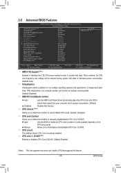
...core 1 x CPU core 2/3/4/5 (Note) } Hard Disk Boot Priority First Boot Device Second Boot Device Third Boot Device Password Check HDD S.M.A.R.T. Manual Allows you install a CPU that supports this function. CPU Core 0 is fixed. When enabled, the CPU core frequency and voltage will be ... heat output from your computer and its power consumption. (Default) Disabled Disables this feature. - 43 - Auto Lets the BIOS to manually enable/disable CPU Core 1/2/3/4/5. CPU Unlock (Note) Allows you to determine whether to unlock hidden CPU cores. (Default: Disabled) CPU...
...core 1 x CPU core 2/3/4/5 (Note) } Hard Disk Boot Priority First Boot Device Second Boot Device Third Boot Device Password Check HDD S.M.A.R.T. Manual Allows you install a CPU that supports this function. CPU Core 0 is fixed. When enabled, the CPU core frequency and voltage will be ... heat output from your computer and its power consumption. (Default) Disabled Disables this feature. - 43 - Auto Lets the BIOS to manually enable/disable CPU Core 1/2/3/4/5. CPU Unlock (Note) Allows you to determine whether to unlock hidden CPU cores. (Default: Disabled) CPU...
Manual
Page 57
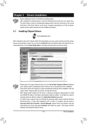
... will restart your optical drive. The driver Autorun screen is installing the drivers. Or click Install Single Items to manually select the drivers you want to manually select the utilities to install. After the system restart, "Xpress Install" will continue to install other drivers. &#... Windows XP operating system, please install the Windows XP Service Pack 1 or later. Or click No if you wish to install new GIGABYTE utilities. Failure to automatically install the utilities. Chapter 3 Drivers Installation • Before installing the drivers, first install the operating system....
... will restart your optical drive. The driver Autorun screen is installing the drivers. Or click Install Single Items to manually select the drivers you want to manually select the utilities to install. After the system restart, "Xpress Install" will continue to install other drivers. &#... Windows XP operating system, please install the Windows XP Service Pack 1 or later. Or click No if you wish to install new GIGABYTE utilities. Failure to automatically install the utilities. Chapter 3 Drivers Installation • Before installing the drivers, first install the operating system....

Manual
Page 58
Drivers Installation - 58 - 3-2 Application Software This page displays all the utilities and applications that GIGABYTE develops and some free software. You can click the Install button on the right of an item to install it. 3-3 Technical Manuals This page provides GIGABYTE's application guides, content descriptions for this driver disk, and the motherboard manuals.
Drivers Installation - 58 - 3-2 Application Software This page displays all the utilities and applications that GIGABYTE develops and some free software. You can click the Install button on the right of an item to install it. 3-3 Technical Manuals This page provides GIGABYTE's application guides, content descriptions for this driver disk, and the motherboard manuals.
Manual
Page 64
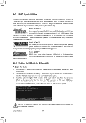
...the key in BIOS Setup. Additionally, this motherboard features the DualBIOS™ design, which enhances protection for GA-870A-UD3 D1 . . . . : BIOS Setup : XpressRecovery2 : Boot Menu : Qflash 12/14/2010-...latest BIOS file from the hassles of system safety, users cannot update the backup BIOS manually. Normally, the system works on the next system boot and copy the BIOS file to...- 64 - Restart the system. 4-2 BIOS Update Utilities GIGABYTE motherboards provide two unique BIOS update tools, Q-Flash™ and @BIOS™. GIGABYTE Q-Flash and @BIOS are easy-to-use FAT32/16/12...
...the key in BIOS Setup. Additionally, this motherboard features the DualBIOS™ design, which enhances protection for GA-870A-UD3 D1 . . . . : BIOS Setup : XpressRecovery2 : Boot Menu : Qflash 12/14/2010-...latest BIOS file from the hassles of system safety, users cannot update the backup BIOS manually. Normally, the system works on the next system boot and copy the BIOS file to...- 64 - Restart the system. 4-2 BIOS Update Utilities GIGABYTE motherboards provide two unique BIOS update tools, Q-Flash™ and @BIOS™. GIGABYTE Q-Flash and @BIOS are easy-to-use FAT32/16/12...

Manual
Page 67
... to do NOT interrupt the Internet connection (for your motherboard is not present on the @BIOS server site, please manually download the BIOS update file from GIGABYTE's website and follow the instructions in a corrupted BIOS or a system that is stable and do so may result ... and TSR (Terminate and Stay Resident) programs. This helps prevent unexpected failures when performing a BIOS update. 2. Do not use the G.O.M. (GIGABYTE Online Management) function when using @BIOS. 4. Load BIOS Defaults after BIOS Update: Select the Load CMOS default after BIOS update check box and...
... to do NOT interrupt the Internet connection (for your motherboard is not present on the @BIOS server site, please manually download the BIOS update file from GIGABYTE's website and follow the instructions in a corrupted BIOS or a system that is stable and do so may result ... and TSR (Terminate and Stay Resident) programs. This helps prevent unexpected failures when performing a BIOS update. 2. Do not use the G.O.M. (GIGABYTE Online Management) function when using @BIOS. 4. Load BIOS Defaults after BIOS Update: Select the Load CMOS default after BIOS update check box and...

Manual
Page 78
... 4). LD No LD Name LD 1 Logical Drive 1 [ LD Define Menu ] RAID Mode Drv RAID 0 0 Stripe Block: 64 KB Gigabyte Boundary: ON Fast Init: ON Cache Mode: WriteThru Port:ID 01:00 02:00 [ Drives Assignments ] Drive Model WDC WD800JD-22LSA0 WDC WD800JD... [[KKeeyyssAAvvaailialabblele]] [h] Up [i] Down [PaUp/PaDn] Switch Page [Space] Change Option [Ctrl+Y] Save [ESC] Exit Figure 5 Appendix - 78 - Create Arrays Manually To create a new array, press to an item for further configuration (Figure 5). Option ROM Utility (c) 2009 Advanced Micro Devices, Inc. To create an array, ...
... 4). LD No LD Name LD 1 Logical Drive 1 [ LD Define Menu ] RAID Mode Drv RAID 0 0 Stripe Block: 64 KB Gigabyte Boundary: ON Fast Init: ON Cache Mode: WriteThru Port:ID 01:00 02:00 [ Drives Assignments ] Drive Model WDC WD800JD-22LSA0 WDC WD800JD... [[KKeeyyssAAvvaailialabblele]] [h] Up [i] Down [PaUp/PaDn] Switch Page [Space] Change Option [Ctrl+Y] Save [ESC] Exit Figure 5 Appendix - 78 - Create Arrays Manually To create a new array, press to an item for further configuration (Figure 5). Option ROM Utility (c) 2009 Advanced Micro Devices, Inc. To create an array, ...
Manual
Page 98
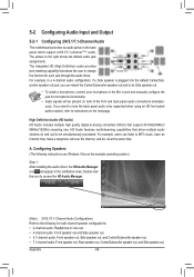
... will be simultaneously processed. Double-click the icon to access the HD Audio Manager. (Note) 2/4/5.1/7.1-Channel Audio Configurations: Refer to the Mic in jack and manually configure the jack for microphone functionality. • Audio signals will appear in the notification area. 5-2 Configuring Audio Input and Output 5-2-1 Configuring 2/4/5.1/7.1-Channel Audio The motherboard...
... will be simultaneously processed. Double-click the icon to access the HD Audio Manager. (Note) 2/4/5.1/7.1-Channel Audio Configurations: Refer to the Mic in jack and manually configure the jack for microphone functionality. • Audio signals will appear in the notification area. 5-2 Configuring Audio Input and Output 5-2-1 Configuring 2/4/5.1/7.1-Channel Audio The motherboard...


