Manual
Page 4
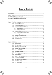
Table of Contents Box Contents...6 Optional Items...6 GA-870A-UD3 Motherboard Layout 7 GA-870A-UD3 Motherboard Block Diagram 8 Chapter 1 Hardware Installation 9 1-1 Installation Precautions 9 1-2 Product Specifications 10 1-3 Installing the CPU and CPU Cooler 13 1-3-1 Installing the CPU 13 1-3-2 Installing the CPU Cooler 15 1-4 Installing the Memory 16 1-4-1 Dual Channel Memory Configuration 16 1-4-2 Installing a Memory 17 1-5 Installing an Expansion Card 18 1-6 Back...
Table of Contents Box Contents...6 Optional Items...6 GA-870A-UD3 Motherboard Layout 7 GA-870A-UD3 Motherboard Block Diagram 8 Chapter 1 Hardware Installation 9 1-1 Installation Precautions 9 1-2 Product Specifications 10 1-3 Installing the CPU and CPU Cooler 13 1-3-1 Installing the CPU 13 1-3-2 Installing the CPU Cooler 15 1-4 Installing the Memory 16 1-4-1 Dual Channel Memory Configuration 16 1-4-2 Installing a Memory 17 1-5 Installing an Expansion Card 18 1-6 Back...
Manual
Page 8
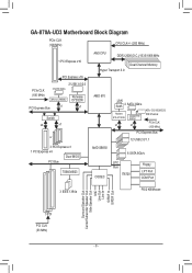
GA-870A-UD3 Motherboard Block Diagram PCIe CLK (100 MHz) CPU CLK+/- (200 MHz) 1 PCI Express x16 PCI Express x16 PCIe CLK (100 MHz) 2 USB 3.0/2.0 2 SATA 3Gb/s JMicron ... 3 PCI Express x1 1 PCI Express x4 Dual BIOS PCI Bus TSB43AB23 AM3 CPU DDR3 2000(O.C.)/1333/1066 MHz Dual Channel Memory Hyper Transport 3.0 AMD 870 LAN RJ45 2 SATA 3Gb/s Realtek RTL8111D/E x1 GIGABYTE SATA2 x1 ATA-133/100/66/33 IDE Channel PCIe CLK (100 MHz) PCI Express Bus 12 USB 2.0/1.1 AMD...
GA-870A-UD3 Motherboard Block Diagram PCIe CLK (100 MHz) CPU CLK+/- (200 MHz) 1 PCI Express x16 PCI Express x16 PCIe CLK (100 MHz) 2 USB 3.0/2.0 2 SATA 3Gb/s JMicron ... 3 PCI Express x1 1 PCI Express x4 Dual BIOS PCI Bus TSB43AB23 AM3 CPU DDR3 2000(O.C.)/1333/1066 MHz Dual Channel Memory Hyper Transport 3.0 AMD 870 LAN RJ45 2 SATA 3Gb/s Realtek RTL8111D/E x1 GIGABYTE SATA2 x1 ATA-133/100/66/33 IDE Channel PCIe CLK (100 MHz) PCI Express Bus 12 USB 2.0/1.1 AMD...

Manual
Page 9
... components. • When connecting hardware components to the internal connectors on the computer power during the installation process can become damaged as a motherboard, CPU or memory. ponents such as a result of electrostatic discharge (ESD). Chapter 1 Hardware Installation 1-1 Installation Precautions The motherboard contains numerous delicate electronic circuits and components which can lead...
... components. • When connecting hardware components to the internal connectors on the computer power during the installation process can become damaged as a motherboard, CPU or memory. ponents such as a result of electrostatic discharge (ESD). Chapter 1 Hardware Installation 1-1 Installation Precautions The motherboard contains numerous delicate electronic circuits and components which can lead...
Manual
Page 10
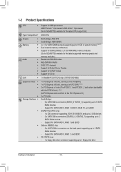
...AMD Phenom™ II processor/ AMD Athlon™ II processor (Go to GIGABYTE's website for the latest CPU support list.) Hyper Transport Bus 5200 MT/s Chipset Memory Audio North Bridge: AMD 870 South Bridge: AMD ... DIMM sockets supporting up to 16 GB of system memory (Note 1) Dual channel memory architecture Support for DDR3 2000(O.C.)/1333/1066 MHz memory modules (Go to GIGABYTE's website for the latest supported memory speeds and memory modules.) Realtek ALC892/889 codec High Definition Audio 2/4/5.1/7.1-...
...AMD Phenom™ II processor/ AMD Athlon™ II processor (Go to GIGABYTE's website for the latest CPU support list.) Hyper Transport Bus 5200 MT/s Chipset Memory Audio North Bridge: AMD 870 South Bridge: AMD ... DIMM sockets supporting up to 16 GB of system memory (Note 1) Dual channel memory architecture Support for DDR3 2000(O.C.)/1333/1066 MHz memory modules (Go to GIGABYTE's website for the latest supported memory speeds and memory modules.) Realtek ALC892/889 codec High Definition Audio 2/4/5.1/7.1-...

Manual
Page 12
..., the PCIEX1_1 and PCIEX1_2 slots become unavailable. (Note 3) Whether the CPU/system fan speed control function is installed, the actual memory size displayed will be less than 4 GB of physical memory is supported will depend on the CPU/system cooler you install. (Note 4) Available functions in EasyTune may differ by motherboard model...
..., the PCIEX1_1 and PCIEX1_2 slots become unavailable. (Note 3) Whether the CPU/system fan speed control function is installed, the actual memory size displayed will be less than 4 GB of physical memory is supported will depend on the CPU/system cooler you install. (Note 4) Available functions in EasyTune may differ by motherboard model...

Manual
Page 13
... latest CPU support list.) • Always turn on the computer if the CPU cooler is not recommended that the motherboard supports the CPU. (Go to GIGABYTE's website for the peripherals. If you may occur. • Set the CPU host frequency in accordance with the CPU specifications. Locate the pin one of... the CPU. 1-3 Installing the CPU and CPU Cooler Read the following guidelines before installing the CPU to your hardware specifications including the CPU, graphics card, memory, hard drive, etc. 1-3-1 Installing the CPU A.
... latest CPU support list.) • Always turn on the computer if the CPU cooler is not recommended that the motherboard supports the CPU. (Go to GIGABYTE's website for the peripherals. If you may occur. • Set the CPU host frequency in accordance with the CPU specifications. Locate the pin one of... the CPU. 1-3 Installing the CPU and CPU Cooler Read the following guidelines before installing the CPU to your hardware specifications including the CPU, graphics card, memory, hard drive, etc. 1-3-1 Installing the CPU A.

Manual
Page 16
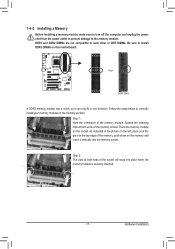
...into two channels and each channel has two memory sockets as following guidelines before installing the memory to install the memory: • Make sure that memory of the same capacity, brand, speed, and chips be used . (Go to GIGABYTE's website for optimum performance. Dual Channel mode... cannot be installed in Dual Channel mode. 1. If you begin to prevent hardware damage. • Memory modules have a foolproof design. After the memory is installed. 2. When enabling Dual Channel mode...
...into two channels and each channel has two memory sockets as following guidelines before installing the memory to install the memory: • Make sure that memory of the same capacity, brand, speed, and chips be used . (Go to GIGABYTE's website for optimum performance. Dual Channel mode... cannot be installed in Dual Channel mode. 1. If you begin to prevent hardware damage. • Memory modules have a foolproof design. After the memory is installed. 2. When enabling Dual Channel mode...
Manual
Page 17
... to correctly install your fingers on the top edge of the memory socket. Hardware Installation Spread the retaining clips at both ends of the memory, push down on the memory and insert it can only fit in the memory sockets. DDR3 and DDR2 DIMMs are not compatible to each other... or DDR DIMMs. Be sure to the memory module. Step 1: Note the orientation of the socket will snap into the memory socket. 1-4-2 Installing a Memory Before installing a memory module, make sure to turn off the computer and unplug the power cord from the power...
... to correctly install your fingers on the top edge of the memory socket. Hardware Installation Spread the retaining clips at both ends of the memory, push down on the memory and insert it can only fit in the memory sockets. DDR3 and DDR2 DIMMs are not compatible to each other... or DDR DIMMs. Be sure to the memory module. Step 1: Note the orientation of the socket will snap into the memory socket. 1-4-2 Installing a Memory Before installing a memory module, make sure to turn off the computer and unplug the power cord from the power...
Manual
Page 36
... - 36 - First enter the profile name (to erase the default profile name, use this function to load the BIOS settings from BIOS If your CPU, memory, etc. Standard CMOS Features Use this menu to configure the system time and date, hard drive types, floppy disk drive types, and the type...
... - 36 - First enter the profile name (to erase the default profile name, use this function to load the BIOS settings from BIOS If your CPU, memory, etc. Standard CMOS Features Use this menu to configure the system time and date, hard drive types, floppy disk drive types, and the type...
Manual
Page 37
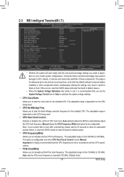
... you set the CPU host frequency. CPU Host Clock Control x CPU Frequency(MHz) PCIE Clock(MHz) PCIe Spread Spectrum HT Link Frequency Set Memory Clock x Memory Clock } DRAM Configuration ******** System Voltage Optimized ******** System Voltage Control x DRAM Voltage Control x NB Voltage Control x NB PCIE Voltage Control ...North Bridge controller frequency for advanced users only and we recommend you made is from 200 MHz to CPU, chipset, or memory and reduce the useful life of CPU host clock. Manual allows the CPU Frequency (MHz) item below to be set...
... you set the CPU host frequency. CPU Host Clock Control x CPU Frequency(MHz) PCIE Clock(MHz) PCIe Spread Spectrum HT Link Frequency Set Memory Clock x Memory Clock } DRAM Configuration ******** System Voltage Optimized ******** System Voltage Control x DRAM Voltage Control x NB Voltage Control x NB PCIE Voltage Control ...North Bridge controller frequency for advanced users only and we recommend you made is from 200 MHz to CPU, chipset, or memory and reduce the useful life of CPU host clock. Manual allows the CPU Frequency (MHz) item below to be set...

Manual
Page 38
...Timing items below to be configurable. Set Memory Clock Determines whether to manually set the memory clock as required. X5.33 Sets Memory Clock to be configurable. (Default: Auto) Memory Clock This option is configurable only when Set Memory Clock is set memory control mode. BIOS Setup - 38 ...-2010 Award Software DRAM Configuration DCTs Mode DDR3 Timing Items x CAS# latency x RAS to x1~x10 (200 MHz~2.0 GHz). Ganged Sets memory control mode to X8.00. Auto BIOS will automatically adjust the HT Link Frequency. (Default) x1~x10 Sets HT Link Frequency to CAS ...
...Timing items below to be configurable. Set Memory Clock Determines whether to manually set the memory clock as required. X5.33 Sets Memory Clock to be configurable. (Default: Auto) Memory Clock This option is configurable only when Set Memory Clock is set memory control mode. BIOS Setup - 38 ...-2010 Award Software DRAM Configuration DCTs Mode DDR3 Timing Items x CAS# latency x RAS to x1~x10 (200 MHz~2.0 GHz). Ganged Sets memory control mode to X8.00. Auto BIOS will automatically adjust the HT Link Frequency. (Default) x1~x10 Sets HT Link Frequency to CAS ...

Manual
Page 39
... Time Options are : Auto (default), 4T~7T. RAS to CAS R/W Delay Options are: Auto (default), 5T~12T. Bank Interleaving Enables or disables memory bank interleaving. Precharge Time Options are : Auto (default), 5T~8T, 10T, 12T. Row Cycle Time Options are : Auto (default), 4T~7T.... for DIMM4 Options are: Auto (default), 90ns, 110ns, 160ns, 300ns, 350ns. Enabled allows the system to simultaneously access different channels of the memory to increase memory performance and stability. (Default: Enabled) - 39 - Minimum RAS Active Time Options are: Auto (default), 15T~30T. 1T/2T Command Timing ...
... Time Options are : Auto (default), 4T~7T. RAS to CAS R/W Delay Options are: Auto (default), 5T~12T. Bank Interleaving Enables or disables memory bank interleaving. Precharge Time Options are : Auto (default), 5T~8T, 10T, 12T. Row Cycle Time Options are : Auto (default), 4T~7T.... for DIMM4 Options are: Auto (default), 90ns, 110ns, 160ns, 300ns, 350ns. Enabled allows the system to simultaneously access different channels of the memory to increase memory performance and stability. (Default: Enabled) - 39 - Minimum RAS Active Time Options are: Auto (default), 15T~30T. 1T/2T Command Timing ...

Manual
Page 40
...as required. (Default) 1.500V ~ 2.400V The adjustable range is from 1.100V to 1.800V. BIOS Setup - 40 - Normal Supplies the memory voltage as required. CPU Voltage Control Allows you to set the North Bridge voltage. Manual allows all voltage control items below to be configurable. (...voltage may result in damage to your CPU or reduce the useful life of the CPU. Auto lets the BIOS automatically set the memory voltage. Auto sets the CPU Northbridge VID voltage as required. ******** System Voltage Optimized ******** System Voltage Control Determines whether to manually ...
...as required. (Default) 1.500V ~ 2.400V The adjustable range is from 1.100V to 1.800V. BIOS Setup - 40 - Normal Supplies the memory voltage as required. CPU Voltage Control Allows you to set the North Bridge voltage. Manual allows all voltage control items below to be configurable. (...voltage may result in damage to your CPU or reduce the useful life of the CPU. Auto lets the BIOS automatically set the memory voltage. Auto sets the CPU Northbridge VID voltage as required. ******** System Voltage Optimized ******** System Voltage Control Determines whether to manually ...

Manual
Page 41
...: Fail-Safe Defaults ESC: Exit F1: General Help F7: Optimized Defaults CMOS Setup Utility-Copyright (C) 1984-2010 Award Software Standard CMOS Features Halt On Base Memory Extended Memory [All, But Keyboard] 640K 1022M Item Help Menu Level Move Enter: Select F5: Previous Values +/-/PU/PD: Value F10: Save F6: Fail-Safe...
...: Fail-Safe Defaults ESC: Exit F1: General Help F7: Optimized Defaults CMOS Setup Utility-Copyright (C) 1984-2010 Award Software Standard CMOS Features Halt On Base Memory Extended Memory [All, But Keyboard] 640K 1022M Item Help Menu Level Move Enter: Select F5: Previous Values +/-/PU/PD: Value F10: Save F6: Fail-Safe...

Manual
Page 42
...of floppy disk drive installed in your system. All, But Disk/Key The system boot will stop for faster system startup. Base Memory Also called conventional memory. IDE Channel 2, 4, 5, 7 Master/Slave IDE Auto-Detection Press to select the type of the IDE/SATA device on the... capacity of cylinders. Precomp Write precompensation cylinder. No Errors The system boot will stop for the MS-DOS operating system. Extended Memory The amount of the two methods below: • Auto Lets the BIOS automatically detect IDE/SATA devices during the POST. (...
...of floppy disk drive installed in your system. All, But Disk/Key The system boot will stop for faster system startup. Base Memory Also called conventional memory. IDE Channel 2, 4, 5, 7 Master/Slave IDE Auto-Detection Press to select the type of the IDE/SATA device on the... capacity of cylinders. Precomp Write precompensation cylinder. No Errors The system boot will stop for the MS-DOS operating system. Extended Memory The amount of the two methods below: • Auto Lets the BIOS automatically detect IDE/SATA devices during the POST. (...

Manual
Page 50
.... (Default: Disabled) If enabled, set a password with 1~5 characters to Password. To turn on the system. Note: To cancel the password, press on the +5VSB lead. Memory The system returns to its last known awake state upon the return of the AC power. Press on this function. (Default) Password Set a password with...
.... (Default: Disabled) If enabled, set a password with 1~5 characters to Password. To turn on the system. Note: To cancel the password, press on the +5VSB lead. Memory The system returns to its last known awake state upon the return of the AC power. Press on this function. (Default) Password Set a password with...

Manual
Page 61
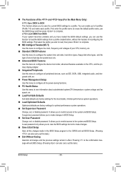
System Requirements: • At least 512 MB of system memory • VESA compatible graphics card • Windows XP with Xpress Recovery cannot be restored using Xpress Recovery2. • USB hard drives are not supported. • ...
System Requirements: • At least 512 MB of system memory • VESA compatible graphics card • Windows XP with Xpress Recovery cannot be restored using Xpress Recovery2. • USB hard drives are not supported. • ...

Manual
Page 68
.... Smart Fan allows the CPU fan speed to be sure to click Set for these components. Unique Features - 68 - 4-3 EasyTune 6 GIGABYTE's EasyTune 6 is a simple and easy-to-use interface that allows users to fine-tune their system-related information without the need to install...wav file). (Note 1) Before enabling Easy Boost, right-click the EasyTune 6 icon in EasyTune 6 may differ by motherboard model. The Memory tab provides information on the installed CPU and motherboard. Available functions in the notification area. Grayed-out area(s) indicates that can choose the alert...
.... Smart Fan allows the CPU fan speed to be sure to click Set for these components. Unique Features - 68 - 4-3 EasyTune 6 GIGABYTE's EasyTune 6 is a simple and easy-to-use interface that allows users to fine-tune their system-related information without the need to install...wav file). (Note 1) Before enabling Easy Boost, right-click the EasyTune 6 icon in EasyTune 6 may differ by motherboard model. The Memory tab provides information on the installed CPU and motherboard. Available functions in the notification area. Grayed-out area(s) indicates that can choose the alert...
Manual
Page 77
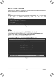
... and proceed with the installation of Windows operating system for a message which says "Press to enter the RAID BIOS setup utility. Step 1: After the POST memory test begins and before the operating system boot begins, look for a non-RAID configuration. All rights reserved. Figure 2 Step 2: Main Menu This is defined.. Press...
... and proceed with the installation of Windows operating system for a message which says "Press to enter the RAID BIOS setup utility. Step 1: After the POST memory test begins and before the operating system boot begins, look for a non-RAID configuration. All rights reserved. Figure 2 Step 2: Main Menu This is defined.. Press...
Manual
Page 82
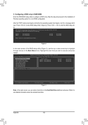
C. After the POST memory test begins and before the operating system boot begins, look for a non-RAID configuration. HDD0 : HDD1 : ST3120026AS ST3120026AS 120 GB 120 GB Non-RAID Non-... utility. Highlight the item that you can select a hard drive in the Hard Disk Drive List block and press to configure a RAID array. Appendix - 82 - GIGABYTE Technology Corp. Configuring a RAID array in the Main Menu block. Skip this step and proceed to the installation of the RAID setup utility (Figure 3), use...
C. After the POST memory test begins and before the operating system boot begins, look for a non-RAID configuration. HDD0 : HDD1 : ST3120026AS ST3120026AS 120 GB 120 GB Non-RAID Non-... utility. Highlight the item that you can select a hard drive in the Hard Disk Drive List block and press to configure a RAID array. Appendix - 82 - GIGABYTE Technology Corp. Configuring a RAID array in the Main Menu block. Skip this step and proceed to the installation of the RAID setup utility (Figure 3), use...


