Manual
Page 4
...Contents Box Contents...6 Optional Items...6 GA-870A-UD3 Motherboard Layout 7 GA-870A-UD3 Motherboard Block Diagram 8 Chapter 1 Hardware Installation 9 1-1 Installation Precautions 9 1-2 Product Specifications 10 1-3 Installing the CPU and CPU Cooler 13 1-3-1 Installing the CPU 13 1-3-2 Installing the CPU Cooler 15 1-4 Installing the Memory 16 1-4-1 Dual Channel Memory Configuration 16 1-4-2 Installing a Memory 17 1-5 Installing an Expansion Card 18 1-6 Back Panel Connectors 19 1-7 Internal Connectors 21 Chapter 2 BIOS Setup 33 2-1 Startup Screen 34 2-2 The Main Menu 35 2-3 MB...
...Contents Box Contents...6 Optional Items...6 GA-870A-UD3 Motherboard Layout 7 GA-870A-UD3 Motherboard Block Diagram 8 Chapter 1 Hardware Installation 9 1-1 Installation Precautions 9 1-2 Product Specifications 10 1-3 Installing the CPU and CPU Cooler 13 1-3-1 Installing the CPU 13 1-3-2 Installing the CPU Cooler 15 1-4 Installing the Memory 16 1-4-1 Dual Channel Memory Configuration 16 1-4-2 Installing a Memory 17 1-5 Installing an Expansion Card 18 1-6 Back Panel Connectors 19 1-7 Internal Connectors 21 Chapter 2 BIOS Setup 33 2-1 Startup Screen 34 2-2 The Main Menu 35 2-3 MB...
Manual
Page 10
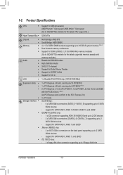
...SATA RAID 0, RAID 1, and JBOD iTE IT8720 chip: - 1 x floppy disk drive connector supporting up to 6 SATA 6Gb/s devices - 1-2 Product Specifications CPU Support for AM3 processors: AMD Phenom™ II processor/ AMD Athlon™ II processor (Go to GIGABYTE's website for the latest CPU support list.) Hyper Transport Bus 5200 MT/s Chipset Memory Audio North Bridge: AMD 870 South Bridge: AMD SB850 4 x 1.5V DDR3 DIMM sockets supporting up to 16 GB of system memory (Note 1) Dual...
...SATA RAID 0, RAID 1, and JBOD iTE IT8720 chip: - 1 x floppy disk drive connector supporting up to 6 SATA 6Gb/s devices - 1-2 Product Specifications CPU Support for AM3 processors: AMD Phenom™ II processor/ AMD Athlon™ II processor (Go to GIGABYTE's website for the latest CPU support list.) Hyper Transport Bus 5200 MT/s Chipset Memory Audio North Bridge: AMD 870 South Bridge: AMD SB850 4 x 1.5V DDR3 DIMM sockets supporting up to 16 GB of system memory (Note 1) Dual...
Manual
Page 18
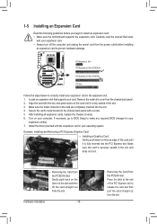
... motherboard supports the expansion card. If necessary, go to BIOS Setup to make any required BIOS changes for your computer. Install the driver provided with your expansion card. • Always turn off the computer and unplug the power cord from the slot. Carefully read the manual that supports your operating system. Remove the metal slot cover from the slot. Align the card with a screw. 5. PCI Express x1 Slot PCI Express x16 Slot (PCIEX16) PCI Express x16 Slot (PCIEX4) PCI Slot...
... motherboard supports the expansion card. If necessary, go to BIOS Setup to make any required BIOS changes for your computer. Install the driver provided with your expansion card. • Always turn off the computer and unplug the power cord from the slot. Carefully read the manual that supports your operating system. Remove the metal slot cover from the slot. Align the card with a screw. 5. PCI Express x1 Slot PCI Express x16 Slot (PCIEX16) PCI Express x16 Slot (PCIEX4) PCI Slot...
Manual
Page 34
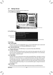
..., Award Software, Inc. After system restart, the device boot order will directly boot from the device configured in Boot Menu is effective for GA-870A-UD3 D1 . . . . : BIOS Setup : XpressRecovery2 : Boot Menu : Qflash 12/14/2010-RX870-SB850-7A66CG0EC-00 Function Keys Function Keys: : POST SCREEN Press the key to enter BIOS Setup first. In Boot Menu, use the up hard drive data using the driver disk, the key can access Boot Menu again to change the first boot device setting as needed. : Q-FLASH Press the key to access the Q-Flash utility directly without entering BIOS Setup...
..., Award Software, Inc. After system restart, the device boot order will directly boot from the device configured in Boot Menu is effective for GA-870A-UD3 D1 . . . . : BIOS Setup : XpressRecovery2 : Boot Menu : Qflash 12/14/2010-RX870-SB850-7A66CG0EC-00 Function Keys Function Keys: : POST SCREEN Press the key to enter BIOS Setup first. In Boot Menu, use the up hard drive data using the driver disk, the key can access Boot Menu again to change the first boot device setting as needed. : Q-FLASH Press the key to access the Q-Flash utility directly without entering BIOS Setup...
Manual
Page 36
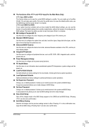
..., hard drive types, floppy disk drive types, and the type of errors that stop the system boot, etc. Advanced BIOS Features Use this menu to configure the device boot order, advanced features available on the CPU, and the primary display adapter. Integrated Peripherals Use this menu to configure all peripheral devices, such as IDE, SATA, USB, integrated audio, and integrated LAN, etc. Power Management Setup Use this function to see information about autodetected system/CPU temperature, system voltage and fan speed, etc...
..., hard drive types, floppy disk drive types, and the type of errors that stop the system boot, etc. Advanced BIOS Features Use this menu to configure the device boot order, advanced features available on the CPU, and the primary display adapter. Integrated Peripherals Use this menu to configure all peripheral devices, such as IDE, SATA, USB, integrated audio, and integrated LAN, etc. Power Management Setup Use this function to see information about autodetected system/CPU temperature, system voltage and fan speed, etc...
Manual
Page 37
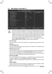
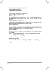
...HT Link Frequency Set Memory Clock x Memory Clock } DRAM Configuration ******** System Voltage Optimized ******** System Voltage Control x DRAM Voltage Control x NB Voltage Control x NB PCIE Voltage Control x CPU NB VID Control x CPU Voltage Control Normal CPU Vcore [Auto] 2800Mhz [Auto] 2000Mhz [Auto] 200 [Auto] [Disabled] [Auto] 2000Mhz [Auto] x6.66 1333Mhz [Press Enter] [Auto] Auto Auto Auto Auto Auto 1.3250V Item Help Menu Level Move Enter: Select F5: Previous Values +/-/PU/PD: Value F10: Save F6: Fail-Safe Defaults ESC: Exit...
...HT Link Frequency Set Memory Clock x Memory Clock } DRAM Configuration ******** System Voltage Optimized ******** System Voltage Control x DRAM Voltage Control x NB Voltage Control x NB PCIE Voltage Control x CPU NB VID Control x CPU Voltage Control Normal CPU Vcore [Auto] 2800Mhz [Auto] 2000Mhz [Auto] 200 [Auto] [Disabled] [Auto] 2000Mhz [Auto] x6.66 1333Mhz [Press Enter] [Auto] Auto Auto Auto Auto Auto 1.3250V Item Help Menu Level Move Enter: Select F5: Previous Values +/-/PU/PD: Value F10: Save F6: Fail-Safe Defaults ESC: Exit...
Manual
Page 43
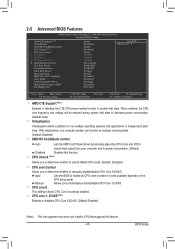
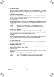
... to HDD Init Display First [Auto] [Disabled] [Auto] [Disabled] [Auto] Enabled Enabled Enabled [Press Enter] [Hard Disk] [CDROM] [Floppy] [Setup] [Disabled] [Disabled] [Enabled] [Disabled] [PCI Slot] Item Help Menu Level Move Enter: Select F5: Previous Values +/-/PU/PD: Value F10: Save F6: Fail-Safe Defaults ESC: Exit F1: General Help F7: Optimized Defaults AMD C1E Support (Note) Enables or disables the C1E CPU power-saving function in independent partitions. 2-5 Advanced BIOS Features CMOS Setup Utility-Copyright (C) 1984-2010 Award Software Advanced BIOS...
... to HDD Init Display First [Auto] [Disabled] [Auto] [Disabled] [Auto] Enabled Enabled Enabled [Press Enter] [Hard Disk] [CDROM] [Floppy] [Setup] [Disabled] [Disabled] [Enabled] [Disabled] [PCI Slot] Item Help Menu Level Move Enter: Select F5: Previous Values +/-/PU/PD: Value F10: Save F6: Fail-Safe Defaults ESC: Exit F1: General Help F7: Optimized Defaults AMD C1E Support (Note) Enables or disables the C1E CPU power-saving function in independent partitions. 2-5 Advanced BIOS Features CMOS Setup Utility-Copyright (C) 1984-2010 Award Software Advanced BIOS...
Manual
Page 44
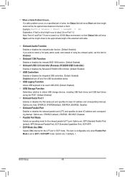
...hard drives. Setup A password is only required for entering the BIOS Setup program. (Default) System A password is corrupted, it up or down on the list. Capability Enables or disables the S.M.A.R.T. (Self Monitoring and Reporting Technology) capability of loading the operating system from the installed PCI graphics card or the PCI Express graphics card. Away Mode allows the system to accept. Options are: Floppy, LS120, Hard Disk, CDROM, ZIP, USB-FDD, USB-ZIP, USB-CDROM, USB-HDD, Legacy LAN, Disabled. After configuring this item, set the password(s) under the Set...
...hard drives. Setup A password is only required for entering the BIOS Setup program. (Default) System A password is corrupted, it up or down on the list. Capability Enables or disables the S.M.A.R.T. (Self Monitoring and Reporting Technology) capability of loading the operating system from the installed PCI graphics card or the PCI Express graphics card. Away Mode allows the system to accept. Options are: Floppy, LS120, Hard Disk, CDROM, ZIP, USB-FDD, USB-ZIP, USB-CDROM, USB-HDD, Legacy LAN, Disabled. After configuring this item, set the password(s) under the Set...
Manual
Page 45
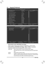
... Setup Utility-Copyright (C) 1984-2010 Award Software Integrated Peripherals OnChip SATA Controller OnChip SATA Type x OnChip SATA Port4/5 Type x OnChip SATA RAID5 Support OnChip SATA3.0 Suuport x OnChip SATA Port as ESP Onboard GSATA/IDE Ctrl Onboard GSATA/IDE Mode Onboard ESATA controller Onboard ESATA Mode Onboard LAN Function Onboard LAN Boot ROM } SMART LAN Onboard Audio Function Onboard 1394 Function Onboard USB 3.0 Controller USB Controllers USB Legacy Function USB Storage Function [Enabled] [Native IDE] IDE Enabled [Enabled] Press Enter...
... Setup Utility-Copyright (C) 1984-2010 Award Software Integrated Peripherals OnChip SATA Controller OnChip SATA Type x OnChip SATA Port4/5 Type x OnChip SATA RAID5 Support OnChip SATA3.0 Suuport x OnChip SATA Port as ESP Onboard GSATA/IDE Ctrl Onboard GSATA/IDE Mode Onboard ESATA controller Onboard ESATA Mode Onboard LAN Function Onboard LAN Boot ROM } SMART LAN Onboard Audio Function Onboard 1394 Function Onboard USB 3.0 Controller USB Controllers USB Legacy Function USB Storage Function [Enabled] [Native IDE] IDE Enabled [Enabled] Press Enter...
Manual
Page 46
... mode. (Default) As SATA Type The mode depends on the OnChip SATA Type settings. RAID/IDE Enables RAID for the SATA controller and configures the SATA controller to as ESP This option is configurable only when OnChip SATA Type is set to RAID or AHCI. IDE Disables RAID for the SATA controller; When set to Disabled, the SATA controller will speed up the hot plug detection of the integrated SATA3_4/SATA3_5 connectors. IDE Configures the SATA controller to IDE mode. (Default) AHCI Configures the SATA controller to AHCI. BIOS Setup - 46 - OnChip SATA Port4/5 Type (AMD...
... mode. (Default) As SATA Type The mode depends on the OnChip SATA Type settings. RAID/IDE Enables RAID for the SATA controller and configures the SATA controller to as ESP This option is configurable only when OnChip SATA Type is set to RAID or AHCI. IDE Disables RAID for the SATA controller; When set to Disabled, the SATA controller will speed up the hot plug detection of the integrated SATA3_4/SATA3_5 connectors. IDE Configures the SATA controller to IDE mode. (Default) AHCI Configures the SATA controller to AHCI. BIOS Setup - 46 - OnChip SATA Port4/5 Type (AMD...
Manual
Page 47
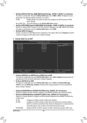
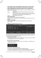
... mode; If no cable problem is activated. - 47 - Cable Length Displays the approximate length of 10/100 Mbps in Windows mode or when the LAN Boot ROM is detected on the Back Panel) Enables or disables RAID for the SATA controller integrated in the JMicron JMB362 chip or configures the SATA controller to activate the boot ROM integrated with the onboard LAN chip. (Default: Disabled) SMART LAN (LAN Cable Diagnostic Function) CMOS Setup Utility-Copyright (C) 1984-2010 Award Software SMART LAN Start detecting at Port..... If no LAN cable is an interface specification...
... mode; If no cable problem is activated. - 47 - Cable Length Displays the approximate length of 10/100 Mbps in Windows mode or when the LAN Boot ROM is detected on the Back Panel) Enables or disables RAID for the SATA controller integrated in the JMicron JMB362 chip or configures the SATA controller to activate the boot ROM integrated with the onboard LAN chip. (Default: Disabled) SMART LAN (LAN Cable Diagnostic Function) CMOS Setup Utility-Copyright (C) 1984-2010 Award Software SMART LAN Start detecting at Port..... If no LAN cable is an interface specification...
Manual
Page 48
...+EPP mode. Options are : 378/IRQ7 (default), 278/IRQ5, 3BC/IRQ7, Disabled. Example: Part1-2 Status = Short / Length = 2m Explanation: A fault or short might occur at about 2m on a specified pair of using the onboard audio, set to detect USB storage devices, including USB flash drives and USB hard drives during the POST. (Default: Enabled) Onboard Serial Port 1 Enables or disables the first serial port and specifies its base I /O address and corresponding interrupt. Onboard 1394 Function Enables or disables the onboard IEEE 1394 function. (Default: Enabled) Onboard USB 3.0 Controller...
...+EPP mode. Options are : 378/IRQ7 (default), 278/IRQ5, 3BC/IRQ7, Disabled. Example: Part1-2 Status = Short / Length = 2m Explanation: A fault or short might occur at about 2m on a specified pair of using the onboard audio, set to detect USB storage devices, including USB flash drives and USB hard drives during the POST. (Default: Enabled) Onboard Serial Port 1 Enables or disables the first serial port and specifies its base I /O address and corresponding interrupt. Onboard 1394 Function Enables or disables the onboard IEEE 1394 function. (Default: Enabled) Onboard USB 3.0 Controller...
Manual
Page 49
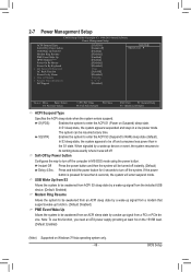
... RAM) sleep state (default). 2-7 Power Management Setup CMOS Setup Utility-Copyright (C) 1984-2010 Award Software Power Management Setup ACPI Suspend Type Soft-Off by Power button USB Wake Up from S3 Modem Ring Resume PME Event Wake Up HPET Support (Note) Power On By Mouse Power On By Keyboard x KB Power ON Password AC Back Function Power-On by a wake-up signal from a PCI or PCIe device. In S1 sleep state, the system appears suspended and stays in the S1 state. BIOS Setup...
... RAM) sleep state (default). 2-7 Power Management Setup CMOS Setup Utility-Copyright (C) 1984-2010 Award Software Power Management Setup ACPI Suspend Type Soft-Off by Power button USB Wake Up from S3 Modem Ring Resume PME Event Wake Up HPET Support (Note) Power On By Mouse Power On By Keyboard x KB Power ON Password AC Back Function Power-On by a wake-up signal from a PCI or PCIe device. In S1 sleep state, the system appears suspended and stays in the S1 state. BIOS Setup...
Manual
Page 52
...type of CPU fan installed and sets the optimal CPU fan control mode. (Default) Voltage Sets Voltage mode for a 4-pin CPU fan. CPU/SYSTEM/POWER FAN Fail Warning Allows the system to control CPU fan speed. System Smart FAN Control Enables or disables the system fan speed control function. Current System/CPU Temperature Displays current system/CPU temperature. Check the fan condition or fan connection when this occurs. (Default: Disabled) CPU Smart FAN Control Enables or disables the CPU fan speed control function. When CPU temperature exceeds the threshold, BIOS will emit warning sound...
...type of CPU fan installed and sets the optimal CPU fan control mode. (Default) Voltage Sets Voltage mode for a 4-pin CPU fan. CPU/SYSTEM/POWER FAN Fail Warning Allows the system to control CPU fan speed. System Smart FAN Control Enables or disables the system fan speed control function. Current System/CPU Temperature Displays current system/CPU temperature. Check the fan condition or fan connection when this occurs. (Default: Disabled) CPU Smart FAN Control Enables or disables the CPU fan speed control function. When CPU temperature exceeds the threshold, BIOS will emit warning sound...
Manual
Page 65
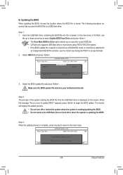
... key during the POST to Drive Enter : Run hi:Move Total size : 0 ESC:Reset Free size : 0 F10:Power Off 3. Step 3: When the update process is displayed on the screen. Update BIOS from Drive Save BIOS to access Q-Flash. 2. B. Make sure the BIOS update file matches your motherboard model. appears, press to update BIOS?" Unique Features Updating the BIOS When updating the BIOS, choose the location where the BIOS file is saved. Q-Flash Utility v2.21 Flash Type/Size MXIC 25L1605/1606 2M Keep0 DfilMe(Is)DfaotuandEnable HDD 0-0 Loa d CMO S Default Enable...
... key during the POST to Drive Enter : Run hi:Move Total size : 0 ESC:Reset Free size : 0 F10:Power Off 3. Step 3: When the update process is displayed on the screen. Update BIOS from Drive Save BIOS to access Q-Flash. 2. B. Make sure the BIOS update file matches your motherboard model. appears, press to update BIOS?" Unique Features Updating the BIOS When updating the BIOS, choose the location where the BIOS file is saved. Q-Flash Utility v2.21 Flash Type/Size MXIC 25L1605/1606 2M Keep0 DfilMe(Is)DfaotuandEnable HDD 0-0 Loa d CMO S Default Enable...
Manual
Page 81
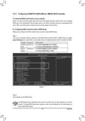
...in BIOS Setup Make sure to RAID CMOS Setup Utility-Copyright (C) 1984-2010 Award Software Integrated Peripherals OnChip SATA Controller OnChip SATA Type x OnChip SATA Port4/5 Type x OnChip SATA RAID5 Support OnChip SATA3.0 Suuport Onboard GSATA/IDE Ctrl Onboard GSATA/IDE Mode Onboard ESATA controller Onboard ESATA Mode Onboard LAN Function Onboard LAN Boot ROM } SMART LAN Onboard Audio Function Onboard 1394 Function Onboard USB 3.0 Controller USB Controllers USB Legacy Function USB Storage Function Onboard Serial Port 1 [Enabled] [Native IDE...
...in BIOS Setup Make sure to RAID CMOS Setup Utility-Copyright (C) 1984-2010 Award Software Integrated Peripherals OnChip SATA Controller OnChip SATA Type x OnChip SATA Port4/5 Type x OnChip SATA RAID5 Support OnChip SATA3.0 Suuport Onboard GSATA/IDE Ctrl Onboard GSATA/IDE Mode Onboard ESATA controller Onboard ESATA Mode Onboard LAN Function Onboard LAN Boot ROM } SMART LAN Onboard Audio Function Onboard 1394 Function Onboard USB 3.0 Controller USB Controllers USB Legacy Function USB Storage Function Onboard Serial Port 1 [Enabled] [Native IDE...
Manual
Page 82
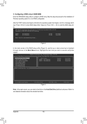
After the POST memory test begins and before the operating system boot begins, look for a non-RAID configuration. PCI Express to enter RAID Setup Utility" (Figure 2). C. Highlight the item that you can select a hard drive in RAID BIOS Enter the RAID BIOS setup utility to enter RAID Setup Utility ... Configuring a RAID array in the Hard Disk Drive List block and press to highlight through choices in the Main Menu block. GIGABYTE Technology Corp. Figure 2 In the main screen of Windows operating system for a message which says "Press to...
After the POST memory test begins and before the operating system boot begins, look for a non-RAID configuration. PCI Express to enter RAID Setup Utility" (Figure 2). C. Highlight the item that you can select a hard drive in RAID BIOS Enter the RAID BIOS setup utility to enter RAID Setup Utility ... Configuring a RAID array in the Hard Disk Drive List block and press to highlight through choices in the Main Menu block. GIGABYTE Technology Corp. Figure 2 In the main screen of Windows operating system for a message which says "Press to...
Manual
Page 87
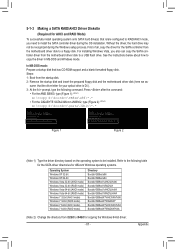
...\RAID\LH64A Bootdrv\SB8xxW7\AHCI\Win7x86 Bootdrv\SB8xxW7\RAID\W7 Bootdrv\SB8xxW7\AHCI\Win7x64 Bootdrv\SB8xxW7\RAID\W764A (Note 2) Change the directory from the startup disk. 2: Remove the startup disk and insert the prepared floppy disk and the motherboard driver disk (here we as- Steps: 1: Boot from \32bit to \64bit for copying the Windows 64-bit driver. - 87 - Refer to a USB flash drive. Press after the command: • For the AMD SB850, type...
...\RAID\LH64A Bootdrv\SB8xxW7\AHCI\Win7x86 Bootdrv\SB8xxW7\RAID\W7 Bootdrv\SB8xxW7\AHCI\Win7x64 Bootdrv\SB8xxW7\RAID\W764A (Note 2) Change the directory from the startup disk. 2: Remove the startup disk and insert the prepared floppy disk and the motherboard driver disk (here we as- Steps: 1: Boot from \32bit to \64bit for copying the Windows 64-bit driver. - 87 - Refer to a USB flash drive. Press after the command: • For the AMD SB850, type...
Manual
Page 90
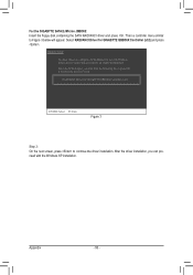
... with Windows, using a device support disk provided by an adapter manufacturer. Windows Setup You have chosen to configure a SCSI Adapter for GIGABYTE GBB36X Controller (x32) ENTER=Select F3=Exit Figure 3 Step 3: On the next screen, press to continue the driver installation. RAID/AHCI Driver for use with the Windows XP installation. After the driver installation, you want from the following list, or press ESC to return to Figure 3 below will appear. Then a controller menu similar...
... with Windows, using a device support disk provided by an adapter manufacturer. Windows Setup You have chosen to configure a SCSI Adapter for GIGABYTE GBB36X Controller (x32) ENTER=Select F3=Exit Figure 3 Step 3: On the next screen, press to continue the driver installation. RAID/AHCI Driver for use with the Windows XP installation. After the driver installation, you want from the following list, or press ESC to return to Figure 3 below will appear. Then a controller menu similar...
Manual
Page 106
...computer problems. (For reference only.) 1 short: System boots successfully 1 long, 9 short: BIOS ROM error 2 short: CMOS setting error Continuous long beeps: Graphics card not inserted properly 1 long, 1 short: Memory or motherboard error Continuous short beeps: Power error 1 long, 2 short: Monitor or graphics card error 1 long, 3 short: Keyboard error Appendix - 106 - Q: In the BIOS Setup program, why are hidden in Chapter 1 to short the jumper to the instructions on after the computer shuts down ? A: For motherboards that have a CMOS_SW button, press this , please turn off...
...computer problems. (For reference only.) 1 short: System boots successfully 1 long, 9 short: BIOS ROM error 2 short: CMOS setting error Continuous long beeps: Graphics card not inserted properly 1 long, 1 short: Memory or motherboard error Continuous short beeps: Power error 1 long, 2 short: Monitor or graphics card error 1 long, 3 short: Keyboard error Appendix - 106 - Q: In the BIOS Setup program, why are hidden in Chapter 1 to short the jumper to the instructions on after the computer shuts down ? A: For motherboards that have a CMOS_SW button, press this , please turn off...


