Manual
Page 1
GA-870A-UD3 AM3 socket motherboard for AMD Phenom™ II processor/ AMD Athlon™ II processor User's Manual Rev. 3001 12ME-870AU3-3001R
GA-870A-UD3 AM3 socket motherboard for AMD Phenom™ II processor/ AMD Athlon™ II processor User's Manual Rev. 3001 12ME-870AU3-3001R
Manual
Page 2
Motherboard GA-870A-UD3 Jan. 14, 2011 Motherboard GA-870A-UD3 Jan. 14, 2011
Motherboard GA-870A-UD3 Jan. 14, 2011 Motherboard GA-870A-UD3 Jan. 14, 2011

Manual
Page 3
... is 1.0. For product-related information, check on our website at: http://www.gigabyte.com Identifying Your Motherboard Revision The revision number on your motherboard revision before updating motherboard BIOS, drivers, or when looking for technical information. No part of this manual..., copied, translated, transmitted, or published in this product, GIGABYTE provides the following types of documentations: For quick set-up of GIGABYTE. All rights reserved. Example: Check your motherboard looks like this manual are legally registered to the specifications and...
... is 1.0. For product-related information, check on our website at: http://www.gigabyte.com Identifying Your Motherboard Revision The revision number on your motherboard revision before updating motherboard BIOS, drivers, or when looking for technical information. No part of this manual..., copied, translated, transmitted, or published in this product, GIGABYTE provides the following types of documentations: For quick set-up of GIGABYTE. All rights reserved. Example: Check your motherboard looks like this manual are legally registered to the specifications and...
Manual
Page 4
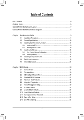
Table of Contents Box Contents...6 Optional Items...6 GA-870A-UD3 Motherboard Layout 7 GA-870A-UD3 Motherboard Block Diagram 8 Chapter 1 Hardware Installation 9 1-1 Installation Precautions 9 1-2 Product Specifications 10 1-3 Installing the CPU and CPU Cooler 13 1-3-1 Installing the CPU 13 1-3-2 Installing the CPU Cooler ...
Table of Contents Box Contents...6 Optional Items...6 GA-870A-UD3 Motherboard Layout 7 GA-870A-UD3 Motherboard Block Diagram 8 Chapter 1 Hardware Installation 9 1-1 Installation Precautions 9 1-2 Product Specifications 10 1-3 Installing the CPU and CPU Cooler 13 1-3-1 Installing the CPU 13 1-3-2 Installing the CPU Cooler ...
Manual
Page 6
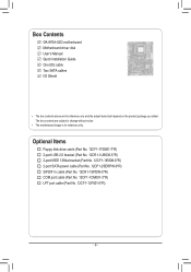
The box contents are for reference only. Box Contents GA-870A-UD3 motherboard Motherboard driver disk User's Manual Quick Installation Guide One IDE cable Two SATA cables I/O Shield • The box contents above are subject to change without notice. • The motherboard image is for reference only and the actual items shall depend on the product package...
The box contents are for reference only. Box Contents GA-870A-UD3 motherboard Motherboard driver disk User's Manual Quick Installation Guide One IDE cable Two SATA cables I/O Shield • The box contents above are subject to change without notice. • The motherboard image is for reference only and the actual items shall depend on the product package...
Manual
Page 7
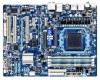
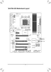
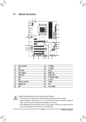
GA-870A-UD3 Motherboard Layout KB_USB RCA_SPDIF CPU_FAN ATX_12V_2X4 USB_1394_ESATA_2 USB_1394_ESATA_1 R_USB USB30_LAN Renesas D720200 AUDIO JMicron JMB362 F_AUDIO PCIEX1_1 Realtek RTL8111D/E PCIEX16 PCIEX1_2 SPDIF_OUT CODEC PCI1 CD_IN SPDIF_IN PCIEX4 PCI2 IT8720 PCI3 COMA LPT Socket AM3 PWR_FAN ATX GA-870A-UD3 AMD 870 DDR3_1 DDR3_2 DDR3_3 DDR3_4 IDE FDD GIGABYTE SATA2 BAT CLR_CMOS AMD SB850 SATA3_5 SATA3_4 SATA3_0 SATA3_3 GSATA2_7 GSATA2_6 SYS_FAN2 F_1394 TSB43AB23 M_BIOS B_BIOS SATA3_1 SATA3_2 F_USB2 F_USB1 F_PANEL SYS_FAN1 - 7 -
GA-870A-UD3 Motherboard Layout KB_USB RCA_SPDIF CPU_FAN ATX_12V_2X4 USB_1394_ESATA_2 USB_1394_ESATA_1 R_USB USB30_LAN Renesas D720200 AUDIO JMicron JMB362 F_AUDIO PCIEX1_1 Realtek RTL8111D/E PCIEX16 PCIEX1_2 SPDIF_OUT CODEC PCI1 CD_IN SPDIF_IN PCIEX4 PCI2 IT8720 PCI3 COMA LPT Socket AM3 PWR_FAN ATX GA-870A-UD3 AMD 870 DDR3_1 DDR3_2 DDR3_3 DDR3_4 IDE FDD GIGABYTE SATA2 BAT CLR_CMOS AMD SB850 SATA3_5 SATA3_4 SATA3_0 SATA3_3 GSATA2_7 GSATA2_6 SYS_FAN2 F_1394 TSB43AB23 M_BIOS B_BIOS SATA3_1 SATA3_2 F_USB2 F_USB1 F_PANEL SYS_FAN1 - 7 -
Manual
Page 8
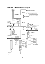
GA-870A-UD3 Motherboard Block Diagram PCIe CLK (100 MHz) CPU CLK+/- (200 MHz) 1 PCI Express x16 PCI Express x16 PCIe CLK (100 MHz) 2 USB 3.0/2.0 2 SATA 3Gb/s JMicron JMB362 ... BIOS PCI Bus TSB43AB23 AM3 CPU DDR3 2000(O.C.)/1333/1066 MHz Dual Channel Memory Hyper Transport 3.0 AMD 870 LAN RJ45 2 SATA 3Gb/s Realtek RTL8111D/E x1 GIGABYTE SATA2 x1 ATA-133/100/66/33 IDE Channel PCIe CLK (100 MHz) PCI Express Bus 12 USB 2.0/1.1 AMD SB850 6 SATA 6Gb/s CODEC LPC Bus...
GA-870A-UD3 Motherboard Block Diagram PCIe CLK (100 MHz) CPU CLK+/- (200 MHz) 1 PCI Express x16 PCI Express x16 PCIe CLK (100 MHz) 2 USB 3.0/2.0 2 SATA 3Gb/s JMicron JMB362 ... BIOS PCI Bus TSB43AB23 AM3 CPU DDR3 2000(O.C.)/1333/1066 MHz Dual Channel Memory Hyper Transport 3.0 AMD 870 LAN RJ45 2 SATA 3Gb/s Realtek RTL8111D/E x1 GIGABYTE SATA2 x1 ATA-133/100/66/33 IDE Channel PCIe CLK (100 MHz) PCI Express Bus 12 USB 2.0/1.1 AMD SB850 6 SATA 6Gb/s CODEC LPC Bus...

Manual
Page 9
... the product, please verify that all cables and power connectors of your dealer. Chapter 1 Hardware Installation 1-1 Installation Precautions The motherboard contains numerous delicate electronic circuits and components which can lead to damage to system components as well as physical harm to the ... electrostatic shielding container. • Before unplugging the power supply cable from the power outlet before installing or removing the motherboard or other hardware components. • When connecting hardware components to the internal connectors on the computer power during the ...
... the product, please verify that all cables and power connectors of your dealer. Chapter 1 Hardware Installation 1-1 Installation Precautions The motherboard contains numerous delicate electronic circuits and components which can lead to damage to system components as well as physical harm to the ... electrostatic shielding container. • Before unplugging the power supply cable from the power outlet before installing or removing the motherboard or other hardware components. • When connecting hardware components to the internal connectors on the computer power during the ...

Manual
Page 12
... PCIEX4 slot. When the PCIEX4 slot is supported will depend on the CPU/system cooler you install. (Note 4) Available functions in EasyTune may differ by motherboard model. Hardware Installation - 12 -
... PCIEX4 slot. When the PCIEX4 slot is supported will depend on the CPU/system cooler you install. (Note 4) Available functions in EasyTune may differ by motherboard model. Hardware Installation - 12 -

Manual
Page 13
...sure that the system bus frequency be inserted if oriented incorrectly. (Or you wish to set beyond the standard specifications, please do so according to GIGABYTE's website for the peripherals. Locate the pin one of the CPU may occur. • Set the CPU host frequency in accordance with the ... standard requirements for the latest CPU support list.) • Always turn on the computer if the CPU cooler is not recommended that the motherboard supports the CPU. (Go to your hardware specifications including the CPU, graphics card, memory, hard drive, etc. 1-3-1 Installing the CPU A.
...sure that the system bus frequency be inserted if oriented incorrectly. (Or you wish to set beyond the standard specifications, please do so according to GIGABYTE's website for the peripherals. Locate the pin one of the CPU may occur. • Set the CPU host frequency in accordance with the ... standard requirements for the latest CPU support list.) • Always turn on the computer if the CPU cooler is not recommended that the motherboard supports the CPU. (Go to your hardware specifications including the CPU, graphics card, memory, hard drive, etc. 1-3-1 Installing the CPU A.
Manual
Page 14
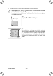
Follow the steps below to correctly install the CPU into the motherboard CPU socket. • Before installing the CPU, make sure to turn off the computer and unplug the power cord from the power outlet to prevent ...
Follow the steps below to correctly install the CPU into the motherboard CPU socket. • Before installing the CPU, make sure to turn off the computer and unplug the power cord from the power outlet to prevent ...
Manual
Page 15
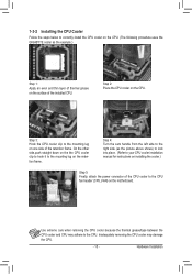
... CPU. Hardware Installation 1-3-2 Installing the CPU Cooler Follow the steps below to correctly install the CPU cooler on the CPU. (The following procedure uses the GIGABYTE cooler as the picture above shows) to lock into place. (Refer to your CPU cooler installation manual for instructions on installing the cooler.) Step 5: Finally...
... CPU. Hardware Installation 1-3-2 Installing the CPU Cooler Follow the steps below to correctly install the CPU cooler on the CPU. (The following procedure uses the GIGABYTE cooler as the picture above shows) to lock into place. (Refer to your CPU cooler installation manual for instructions on installing the cooler.) Step 5: Finally...

Manual
Page 16
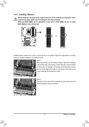
... memory sockets are unable to insert the memory, switch the direction. 1-4-1 Dual Channel Memory Configuration This motherboard provides four DDR3 memory sockets and supports Dual Channel Technology. A memory module can be used . (Go to GIGABYTE's website for optimum performance. After the memory is recommended that memory of the same capacity, brand, speed...
... memory sockets are unable to insert the memory, switch the direction. 1-4-1 Dual Channel Memory Configuration This motherboard provides four DDR3 memory sockets and supports Dual Channel Technology. A memory module can be used . (Go to GIGABYTE's website for optimum performance. After the memory is recommended that memory of the same capacity, brand, speed...
Manual
Page 17
..., make sure to turn off the computer and unplug the power cord from the power outlet to prevent damage to install DDR3 DIMMs on this motherboard. Notch DDR3 DIMM A DDR3 memory module has a notch, so it vertically into place when the memory module is securely inserted. - 17 - DDR3 and DDR2 DIMMs...
..., make sure to turn off the computer and unplug the power cord from the power outlet to prevent damage to install DDR3 DIMMs on this motherboard. Notch DDR3 DIMM A DDR3 memory module has a notch, so it vertically into place when the memory module is securely inserted. - 17 - DDR3 and DDR2 DIMMs...
Manual
Page 18
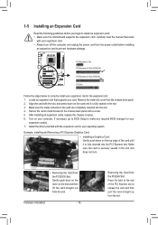
... the slot. 3. Hardware Installation - 18 - • Removing the Card from the power outlet before you begin to install an expansion card: • Make sure the motherboard supports the expansion card. PCI Express x1 Slot PCI Express x16 Slot (PCIEX16) PCI Express x16 Slot (PCIEX4) PCI Slot Follow the steps below to...
... the slot. 3. Hardware Installation - 18 - • Removing the Card from the power outlet before you begin to install an expansion card: • Make sure the motherboard supports the expansion card. PCI Express x1 Slot PCI Express x16 Slot (PCIEX16) PCI Express x16 Slot (PCIEX4) PCI Slot Follow the steps below to...
Manual
Page 19
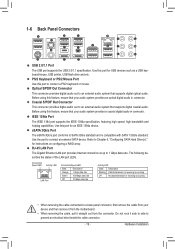
... it straight out from the connector. PS/2 Keyboard or PS/2 Mouse Port Use this feature, ensure that your device and then remove it from the motherboard. • When removing the cable, pull it side to side to 1 Gbps data rate. Before using this feature, ensure that your audio system provides a coaxial...
... it straight out from the connector. PS/2 Keyboard or PS/2 Mouse Port Use this feature, ensure that your device and then remove it from the motherboard. • When removing the cable, pull it side to side to 1 Gbps data rate. Before using this feature, ensure that your audio system provides a coaxial...
Manual
Page 21
... 13) CD_IN 14) SPDIF_IN 15) SPDIF_OUT 16) F_USB1/F_USB2 17) F_1394 18) COMA 19) LPT 20) CLR_CMOS Read the following guidelines before turning on the motherboard. - 21 - Unplug the power cord from the power outlet to prevent damage to the devices. • After installing the device and before connecting external devices...
... 13) CD_IN 14) SPDIF_IN 15) SPDIF_OUT 16) F_USB1/F_USB2 17) F_1394 18) COMA 19) LPT 20) CLR_CMOS Read the following guidelines before turning on the motherboard. - 21 - Unplug the power cord from the power outlet to prevent damage to the devices. • After installing the device and before connecting external devices...
Manual
Page 22
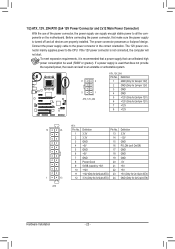
... power connector mainly supplies power to the power connector in the correct orientation. If a power supply is turned off and all the components on the motherboard.
... power connector mainly supplies power to the power connector in the correct orientation. If a power supply is turned off and all the components on the motherboard.

Manual
Page 23
.... Overheating may hang. • These fan headers are : 360 KB, 720 KB, 1.2 MB, 1.44 MB, and 2.88 MB. The motherboard supports CPU fan speed control, which requires the use of different color. Hardware Installation The types of the connector and the floppy disk drive cable... SYS_FAN1: Pin No. Before connecting a floppy disk drive, be installed inside the chassis. 3/4/5) CPU_FAN/SYS_FAN1/SYS_FAN2/PWR_FAN (Fan Headers) The motherboard has a 4-pin CPU fan header (CPU_FAN), a 4-pin (SYS_FAN1) and a 3-pin (SYS_ FAN2) system fan headers, and a 3-pin power fan header (PWR_FAN).
.... Overheating may hang. • These fan headers are : 360 KB, 720 KB, 1.2 MB, 1.44 MB, and 2.88 MB. The motherboard supports CPU fan speed control, which requires the use of different color. Hardware Installation The types of the connector and the floppy disk drive cable... SYS_FAN1: Pin No. Before connecting a floppy disk drive, be installed inside the chassis. 3/4/5) CPU_FAN/SYS_FAN1/SYS_FAN2/PWR_FAN (Fan Headers) The motherboard has a 4-pin CPU fan header (CPU_FAN), a 4-pin (SYS_FAN1) and a 3-pin (SYS_ FAN2) system fan headers, and a 3-pin power fan header (PWR_FAN).
Manual
Page 27
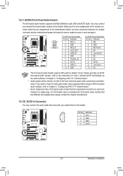
... (L) 10 GND 10 NC • The front panel audio header supports HD audio by default. Incorrect connection between the module connector and the motherboard header will be present on each wire instead of the motherboard header. Make sure the wire assignments of the module connector match the pin assignments of a single plug.
... (L) 10 GND 10 NC • The front panel audio header supports HD audio by default. Incorrect connection between the module connector and the motherboard header will be present on each wire instead of the motherboard header. Make sure the wire assignments of the module connector match the pin assignments of a single plug.


