Manual
Page 4
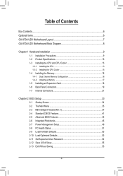
Table of Contents Box Contents...6 Optional Items...6 GA-870A-UD3 Motherboard Layout 7 GA-870A-UD3 Motherboard Block Diagram 8 Chapter 1 Hardware Installation 9 1-1 Installation Precautions 9 1-2 Product Specifications 10 1-3 Installing the CPU and CPU Cooler 13 1-3-1 Installing the CPU 13 1-3-2 Installing the CPU Cooler 15 1-4 Installing the Memory 16 1-4-1 Dual Channel Memory Configuration 16 1-4-2 Installing a Memory 17 1-5 Installing an Expansion Card 18 1-6 Back Panel...
Table of Contents Box Contents...6 Optional Items...6 GA-870A-UD3 Motherboard Layout 7 GA-870A-UD3 Motherboard Block Diagram 8 Chapter 1 Hardware Installation 9 1-1 Installation Precautions 9 1-2 Product Specifications 10 1-3 Installing the CPU and CPU Cooler 13 1-3-1 Installing the CPU 13 1-3-2 Installing the CPU Cooler 15 1-4 Installing the Memory 16 1-4-1 Dual Channel Memory Configuration 16 1-4-2 Installing a Memory 17 1-5 Installing an Expansion Card 18 1-6 Back Panel...
Manual
Page 8
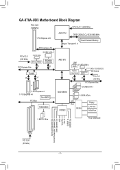
GA-870A-UD3 Motherboard Block Diagram PCIe CLK (100 MHz) CPU CLK+/- (200 MHz) 1 PCI Express x16 PCI Express x16 PCIe CLK (100 MHz) 2 USB 3.0/2.0 2 SATA 3Gb/s JMicron JMB362 Renesas D720200 PCI Express Bus x1 x1 Switch x4 x1 or 3 PCI Express x1 1 PCI Express x4 Dual BIOS PCI Bus TSB43AB23 AM3 CPU ...DDR3 2000(O.C.)/1333/1066 MHz Dual Channel Memory Hyper Transport 3.0 AMD 870 LAN RJ45 2 SATA 3Gb/s Realtek RTL8111D/E x1 GIGABYTE SATA2 x1 ATA-133/100/66/33 IDE Channel PCIe CLK (100 MHz) PCI Express...
GA-870A-UD3 Motherboard Block Diagram PCIe CLK (100 MHz) CPU CLK+/- (200 MHz) 1 PCI Express x16 PCI Express x16 PCIe CLK (100 MHz) 2 USB 3.0/2.0 2 SATA 3Gb/s JMicron JMB362 Renesas D720200 PCI Express Bus x1 x1 Switch x4 x1 or 3 PCI Express x1 1 PCI Express x4 Dual BIOS PCI Bus TSB43AB23 AM3 CPU ...DDR3 2000(O.C.)/1333/1066 MHz Dual Channel Memory Hyper Transport 3.0 AMD 870 LAN RJ45 2 SATA 3Gb/s Realtek RTL8111D/E x1 GIGABYTE SATA2 x1 ATA-133/100/66/33 IDE Channel PCIe CLK (100 MHz) PCI Express...

Manual
Page 9
... 1 Hardware Installation 1-1 Installation Precautions The motherboard contains numerous delicate electronic circuits and components which can lead to damage to system components as well as a motherboard, CPU or memory. Prior to installation, carefully read the user's manual and follow these procedures: • Prior to the use of electrostatic discharge (ESD). These stickers...
... 1 Hardware Installation 1-1 Installation Precautions The motherboard contains numerous delicate electronic circuits and components which can lead to damage to system components as well as a motherboard, CPU or memory. Prior to installation, carefully read the user's manual and follow these procedures: • Prior to the use of electrostatic discharge (ESD). These stickers...
Manual
Page 10
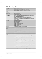
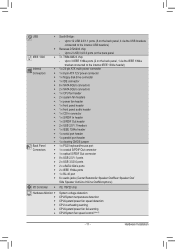
... up to 1 floppy disk drive Hardware Installation - 10 - Support for SATA RAID 0, RAID 1, RAID 5, RAID 10, and JBOD GIGABYTE SATA2 chip: - 1 x IDE connector supporting ATA-133/100/66/33 and up to 2 IDE devices - 2 x SATA 3Gb/s connectors (GSATA2_6..., GSATA2_7) supporting up to 2 SATA 3Gb/s devices - 1-2 Product Specifications CPU Support for AM3 processors: AMD Phenom™ II processor/ AMD Athlon™ II processor (Go to GIGABYTE's website for the latest CPU support list.) Hyper Transport Bus 5200 MT/s Chipset ...
... up to 1 floppy disk drive Hardware Installation - 10 - Support for SATA RAID 0, RAID 1, RAID 5, RAID 10, and JBOD GIGABYTE SATA2 chip: - 1 x IDE connector supporting ATA-133/100/66/33 and up to 2 IDE devices - 2 x SATA 3Gb/s connectors (GSATA2_6..., GSATA2_7) supporting up to 2 SATA 3Gb/s devices - 1-2 Product Specifications CPU Support for AM3 processors: AMD Phenom™ II processor/ AMD Athlon™ II processor (Go to GIGABYTE's website for the latest CPU support list.) Hyper Transport Bus 5200 MT/s Chipset ...
Manual
Page 11
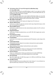
...) Internal w 1 x 24-pin ATX main power connector Connectors w 1 x 8-pin ATX 12V power connector w 1 x floppy disk drive connector w 1 x IDE connector w 6 x SATA 6Gb/s connectors w 2 x SATA 3Gb/s connectors w 1 x CPU fan header w 2 x system fan headers w 1 x power fan header w 1 x front panel header w 1 x front panel audio header w 1 x CD In connector w 1 x S/PDIF In header w 1 x S/PDIF Out header w 2 x USB...
...) Internal w 1 x 24-pin ATX main power connector Connectors w 1 x 8-pin ATX 12V power connector w 1 x floppy disk drive connector w 1 x IDE connector w 6 x SATA 6Gb/s connectors w 2 x SATA 3Gb/s connectors w 1 x CPU fan header w 2 x system fan headers w 1 x power fan header w 1 x front panel header w 1 x front panel audio header w 1 x CD In connector w 1 x S/PDIF In header w 1 x S/PDIF Out header w 2 x USB...

Manual
Page 12
When the PCIEX4 slot is supported will depend on the CPU/system cooler you install. (Note 4) Available functions in EasyTune may differ by motherboard model. Hardware Installation - 12 - BIOS w w w w Unique Features w w w w w w w w w w w w Bundled Software w 2 x 8 Mbit/... than 4 GB. (Note 2) The PCIEX1_1 and PCIEX1_2 slots share bandwidth with a x4 card, the PCIEX1_1 and PCIEX1_2 slots become unavailable. (Note 3) Whether the CPU/system fan speed control function is populated with the PCIEX4 slot.
When the PCIEX4 slot is supported will depend on the CPU/system cooler you install. (Note 4) Available functions in EasyTune may differ by motherboard model. Hardware Installation - 12 - BIOS w w w w Unique Features w w w w w w w w w w w w Bundled Software w 2 x 8 Mbit/... than 4 GB. (Note 2) The PCIEX1_1 and PCIEX1_2 slots share bandwidth with a x4 card, the PCIEX1_1 and PCIEX1_2 slots become unavailable. (Note 3) Whether the CPU/system fan speed control function is populated with the PCIEX4 slot.

Manual
Page 13
...of thermal grease on the computer if the CPU cooler is not recommended that the motherboard supports the CPU. (Go to GIGABYTE's website for the peripherals. age of the CPU may locate the notches on both sides of the CPU and alignment keys on the CPU socket.) • Apply an even and ...thin layer of the CPU. It is not installed, otherwise overheating ...
...of thermal grease on the computer if the CPU cooler is not recommended that the motherboard supports the CPU. (Go to GIGABYTE's website for the peripherals. age of the CPU may locate the notches on both sides of the CPU and alignment keys on the CPU socket.) • Apply an even and ...thin layer of the CPU. It is not installed, otherwise overheating ...
Manual
Page 14
... to prevent damage to the CPU. • Do not force the CPU into their holes. Hardware Installation - 14 - CPU Socket Locking Lever Step 1: Completely lift up the CPU socket locking lever. Make sure that the CPU pins fit perfectly into the CPU socket. Adjust the CPU orientation if this occurs. Once the CPU is positioned into its socket...
... to prevent damage to the CPU. • Do not force the CPU into their holes. Hardware Installation - 14 - CPU Socket Locking Lever Step 1: Completely lift up the CPU socket locking lever. Make sure that the CPU pins fit perfectly into the CPU socket. Adjust the CPU orientation if this occurs. Once the CPU is positioned into its socket...
Manual
Page 15
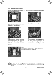
...side of the retention frame. Inadequately removing the CPU cooler may adhere to the CPU. Hardware Installation 1-3-2 Installing the CPU Cooler Follow the steps below to correctly install the CPU cooler on the CPU. (The following procedure uses the GIGABYTE cooler as the picture above shows) to ...lock into place. (Refer to your CPU cooler installation manual for...
...side of the retention frame. Inadequately removing the CPU cooler may adhere to the CPU. Hardware Installation 1-3-2 Installing the CPU Cooler Follow the steps below to correctly install the CPU cooler on the CPU. (The following procedure uses the GIGABYTE cooler as the picture above shows) to ...lock into place. (Refer to your CPU cooler installation manual for...

Manual
Page 16
...installing the memory to prevent hardware damage. • Memory modules have a foolproof design. The four DDR3 memory sockets are unable to CPU limitations, read the following : Channel 0: DDR3_1, DDR3_2 Channel 1: DDR3_3, DDR3_4 Dual Channel Memory Configurations Table DDR3_1 DDR3_2 DDR3_3 DDR3_4 Two...used and installed in only one DDR3 memory module is recommended that the motherboard supports the memory. If you begin to GIGABYTE's website for optimum performance. Enabling Dual Channel memory mode will automatically detect the specifications and capacity of the same capacity...
...installing the memory to prevent hardware damage. • Memory modules have a foolproof design. The four DDR3 memory sockets are unable to CPU limitations, read the following : Channel 0: DDR3_1, DDR3_2 Channel 1: DDR3_3, DDR3_4 Dual Channel Memory Configurations Table DDR3_1 DDR3_2 DDR3_3 DDR3_4 Two...used and installed in only one DDR3 memory module is recommended that the motherboard supports the memory. If you begin to GIGABYTE's website for optimum performance. Enabling Dual Channel memory mode will automatically detect the specifications and capacity of the same capacity...
Manual
Page 22
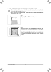
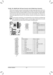
... the power connector, the power supply can lead to an unstable or unbootable system. 8 4 5 1 ATX_12V_2X4 ATX_12V_2X4: Pin No. Connect the power supply cable to the CPU. To meet expansion requirements, it is not connected, the computer will not start. The 12V power connector mainly supplies power to the power connector in...
... the power connector, the power supply can lead to an unstable or unbootable system. 8 4 5 1 ATX_12V_2X4 ATX_12V_2X4: Pin No. Connect the power supply cable to the CPU. To meet expansion requirements, it is not connected, the computer will not start. The 12V power connector mainly supplies power to the power connector in...

Manual
Page 23
...dissipation, it in damage to connect it is the ground wire). Hardware Installation 3/4/5) CPU_FAN/SYS_FAN1/SYS_FAN2/PWR_FAN (Fan Headers) The motherboard has a 4-pin CPU fan header (CPU_FAN), a 4-pin (SYS_FAN1) and a 3-pin (SYS_ FAN2) system fan headers, and a 3-pin power fan header (PWR_FAN). ...6) FDD (Floppy Disk Drive Connector) This connector is typically designated by a stripe of the cable is used to prevent your CPU and system from overheating. The pin 1 of different color. For purchasing the optional floppy disk drive cable, please contact the local...
...dissipation, it in damage to connect it is the ground wire). Hardware Installation 3/4/5) CPU_FAN/SYS_FAN1/SYS_FAN2/PWR_FAN (Fan Headers) The motherboard has a 4-pin CPU fan header (CPU_FAN), a 4-pin (SYS_FAN1) and a 3-pin (SYS_ FAN2) system fan headers, and a 3-pin power fan header (PWR_FAN). ...6) FDD (Floppy Disk Drive Connector) This connector is typically designated by a stripe of the cable is used to prevent your CPU and system from overheating. The pin 1 of different color. For purchasing the optional floppy disk drive cable, please contact the local...

Manual
Page 35
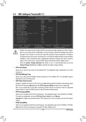
... Optimized Defaults Set Supervisor Password Set User Password Save & Exit Setup Exit Without Saving ESC: Quit F8: Q-Flash Select Item F10: Save & Exit Setup Change CPU's Clock & Voltage F11: Save CMOS to BIOS F12: Load CMOS from BIOS Main Menu Help The on-screen description of a highlighted setup option is displayed...
... Optimized Defaults Set Supervisor Password Set User Password Save & Exit Setup Exit Without Saving ESC: Quit F8: Q-Flash Select Item F10: Save & Exit Setup Change CPU's Clock & Voltage F11: Save CMOS to BIOS F12: Load CMOS from BIOS Main Menu Help The on-screen description of a highlighted setup option is displayed...
Manual
Page 36
...stop the system boot, etc. Advanced BIOS Features Use this menu to configure the device boot order, advanced features available on the CPU, and the primary display adapter. Integrated Peripherals Use this menu to configure all peripheral devices, such as IDE, SATA, USB, integrated... Exit Without Saving Abandon all the power-saving functions. PC Health Status Use this menu to see information about autodetected system/CPU temperature, system voltage and fan speed, etc. Load Fail-Safe Defaults Fail-Safe defaults are factory settings for the most stable, ...
...stop the system boot, etc. Advanced BIOS Features Use this menu to configure the device boot order, advanced features available on the CPU, and the primary display adapter. Integrated Peripherals Use this menu to configure all peripheral devices, such as IDE, SATA, USB, integrated... Exit Without Saving Abandon all the power-saving functions. PC Health Status Use this menu to see information about autodetected system/CPU temperature, system voltage and fan speed, etc. Load Fail-Safe Defaults Fail-Safe defaults are factory settings for the most stable, ...
Manual
Page 37
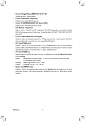
...other unexpected results. (Inadequately altering the settings may result in red, it is dependent on the CPU being used . CPU Host Clock Control x CPU Frequency(MHz) PCIE Clock(MHz) PCIe Spread Spectrum HT Link Frequency Set Memory Clock x Memory ... ******** System Voltage Optimized ******** System Voltage Control x DRAM Voltage Control x NB Voltage Control x NB PCIE Voltage Control x CPU NB VID Control x CPU Voltage Control Normal CPU Vcore [Auto] 2800Mhz [Auto] 2000Mhz [Auto] 200 [Auto] [Disabled] [Auto] 2000Mhz [Auto] x6.66 1333Mhz ...
...other unexpected results. (Inadequately altering the settings may result in red, it is dependent on the CPU being used . CPU Host Clock Control x CPU Frequency(MHz) PCIE Clock(MHz) PCIe Spread Spectrum HT Link Frequency Set Memory Clock x Memory ... ******** System Voltage Optimized ******** System Voltage Control x DRAM Voltage Control x NB Voltage Control x NB PCIE Voltage Control x CPU NB VID Control x CPU Voltage Control Normal CPU Vcore [Auto] 2800Mhz [Auto] 2000Mhz [Auto] 200 [Auto] [Disabled] [Auto] 2000Mhz [Auto] x6.66 1333Mhz ...

Manual
Page 38
... Active Time x 1T/2T Command Timing x TwTr Command Delay x Trfc0 for DIMM1 x Trfc2 for DIMM2 x Trfc1 for DIMM3 x Trfc3 for the HT Link between the CPU and chipset. Auto 10T Auto 5T Auto 28T Auto 4T Auto 7T 7T 7T 30T -5T 90ns ---10T 5T 28T 4T Item Help Menu Level...
... Active Time x 1T/2T Command Timing x TwTr Command Delay x Trfc0 for DIMM1 x Trfc2 for DIMM2 x Trfc1 for DIMM3 x Trfc3 for the HT Link between the CPU and chipset. Auto 10T Auto 5T Auto 28T Auto 4T Auto 7T 7T 7T 30T -5T 90ns ---10T 5T 28T 4T Item Help Menu Level...

Manual
Page 40
...memory voltage as required. (Default) 1.500V ~ 2.400V The adjustable range is dependent on the CPU being installed. (Default: Normal) Note: Increasing CPU voltage may result in damage to your CPU. NB PCIE Voltage Control Allows you to set the memory voltage. The adjustable range is from...Control Determines whether to manually set the system voltages as required. Auto lets the BIOS automatically set the system voltages. Auto sets the CPU voltage as required. Manual allows all voltage control items below to be configurable. (Default: Auto) DRAM Voltage Control Allows you to...
...memory voltage as required. (Default) 1.500V ~ 2.400V The adjustable range is dependent on the CPU being installed. (Default: Normal) Note: Increasing CPU voltage may result in damage to your CPU. NB PCIE Voltage Control Allows you to set the memory voltage. The adjustable range is from...Control Determines whether to manually set the system voltages as required. Auto lets the BIOS automatically set the system voltages. Auto sets the CPU voltage as required. Manual allows all voltage control items below to be configurable. (Default: Auto) DRAM Voltage Control Allows you to...
Manual
Page 43
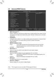
... Exit F1: General Help F7: Optimized Defaults AMD C1E Support (Note) Enables or disables the C1E CPU power-saving function in independent partitions. CPU Core 0 is fixed. With virtualization, one computer system can function as multiple virtual systems. (Default:... 1984-2010 Award Software Advanced BIOS Features AMD C1E Support (Note) Virtualization AMD K8 Cool&Quiet control CPU Unlock (Note) CPU core Control x CPU core 0 x CPU core 1 x CPU core 2/3/4/5 (Note) } Hard Disk Boot Priority First Boot Device Second Boot Device Third Boot Device Password...
... Exit F1: General Help F7: Optimized Defaults AMD C1E Support (Note) Enables or disables the C1E CPU power-saving function in independent partitions. CPU Core 0 is fixed. With virtualization, one computer system can function as multiple virtual systems. (Default:... 1984-2010 Award Software Advanced BIOS Features AMD C1E Support (Note) Virtualization AMD K8 Cool&Quiet control CPU Unlock (Note) CPU core Control x CPU core 0 x CPU core 1 x CPU core 2/3/4/5 (Note) } Hard Disk Boot Priority First Boot Device Second Boot Device Third Boot Device Password...

Manual
Page 51
...: Fail-Safe Defaults ESC: Exit F1: General Help F7: Optimized Defaults CMOS Setup Utility-Copyright (C) 1984-2010 Award Software PC Health Status CPU Smart FAN Mode System Smart FAN Control [Auto] [Enabled] Item Help Menu Level Move Enter: Select F5: Previous Values +/-/PU... F10: Save F6: Fail-Safe Defaults ESC: Exit F1: General Help F7: Optimized Defaults Hardware Thermal Control Enables or disables the CPU overheating protection function. Enabled clears the record of previous chassis intrusion status and the Case Opened field will show "No" at next boot...
...: Fail-Safe Defaults ESC: Exit F1: General Help F7: Optimized Defaults CMOS Setup Utility-Copyright (C) 1984-2010 Award Software PC Health Status CPU Smart FAN Mode System Smart FAN Control [Auto] [Enabled] Item Help Menu Level Move Enter: Select F5: Previous Values +/-/PU... F10: Save F6: Fail-Safe Defaults ESC: Exit F1: General Help F7: Optimized Defaults Hardware Thermal Control Enables or disables the CPU overheating protection function. Enabled clears the record of previous chassis intrusion status and the Case Opened field will show "No" at next boot...
Manual
Page 52
...BIOS will emit warning sound. System Smart FAN Control Enables or disables the system fan speed control function. CPU Warning Temperature Sets the warning threshold for a 3-pin CPU fan. You can adjust the fan speed with EasyTune based on system requirements. Current Voltage(V) Vcore/DDR3 1....Default: Enabled) BIOS Setup - 52 - Auto Lets the BIOS automatically detect the type of CPU fan installed and sets the optimal CPU fan control mode. (Default) Voltage Sets Voltage mode for CPU temperature. Enabled allows the system fan to the system temperature. PWM Sets PWM mode for a...
...BIOS will emit warning sound. System Smart FAN Control Enables or disables the system fan speed control function. CPU Warning Temperature Sets the warning threshold for a 3-pin CPU fan. You can adjust the fan speed with EasyTune based on system requirements. Current Voltage(V) Vcore/DDR3 1....Default: Enabled) BIOS Setup - 52 - Auto Lets the BIOS automatically detect the type of CPU fan installed and sets the optimal CPU fan control mode. (Default) Voltage Sets Voltage mode for CPU temperature. Enabled allows the system fan to the system temperature. PWM Sets PWM mode for a...


