
Manual
Page 3
...rights reserved. For product-related information, check on our website at: http://www.gigabyte.com Identifying Your Motherboard Revision The revision number on your motherboard revision before updating motherboard BIOS, drivers, or when looking for technical information. Disclaimer Information in this manual is ...registered to the specifications and features in any form or by copyright laws and is 1.0. The trademarks mentioned in this product, GIGABYTE provides the following types of documentations: For quick set-up of the motherboard is the property of this manual ...
...rights reserved. For product-related information, check on our website at: http://www.gigabyte.com Identifying Your Motherboard Revision The revision number on your motherboard revision before updating motherboard BIOS, drivers, or when looking for technical information. Disclaimer Information in this manual is ...registered to the specifications and features in any form or by copyright laws and is 1.0. The trademarks mentioned in this product, GIGABYTE provides the following types of documentations: For quick set-up of the motherboard is the property of this manual ...
Manual
Page 4
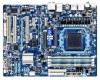
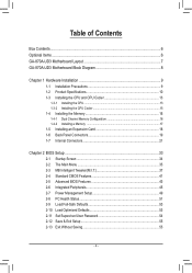
Table of Contents Box Contents...6 Optional Items...6 GA-870A-UD3 Motherboard Layout 7 GA-870A-UD3 Motherboard Block Diagram 8 Chapter 1 Hardware Installation 9 1-1 Installation Precautions 9 1-2 Product Specifications 10 1-3 Installing the CPU and CPU ... an Expansion Card 18 1-6 Back Panel Connectors 19 1-7 Internal Connectors 21 Chapter 2 BIOS Setup 33 2-1 Startup Screen 34 2-2 The Main Menu 35 2-3 MB Intelligent Tweaker(M.I.T 37 2-4 Standard CMOS Features 41 2-5 Advanced BIOS Features 43 2-6 Integrated Peripherals 45 2-7 Power Management Setup 49 2-8 PC Health Status ...
Table of Contents Box Contents...6 Optional Items...6 GA-870A-UD3 Motherboard Layout 7 GA-870A-UD3 Motherboard Block Diagram 8 Chapter 1 Hardware Installation 9 1-1 Installation Precautions 9 1-2 Product Specifications 10 1-3 Installing the CPU and CPU ... an Expansion Card 18 1-6 Back Panel Connectors 19 1-7 Internal Connectors 21 Chapter 2 BIOS Setup 33 2-1 Startup Screen 34 2-2 The Main Menu 35 2-3 MB Intelligent Tweaker(M.I.T 37 2-4 Standard CMOS Features 41 2-5 Advanced BIOS Features 43 2-6 Integrated Peripherals 45 2-7 Power Management Setup 49 2-8 PC Health Status ...
Manual
Page 5
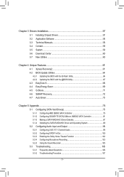
... New Utilities...60 Chapter 4 Unique Features 61 4-1 Xpress Recovery2 61 4-2 BIOS Update Utilities 64 4-2-1 Updating the BIOS with the Q-Flash Utility 64 4-2-2 Updating the BIOS with the @BIOS Utility 67 4-3 EasyTune 6...68 4-4 Easy Energy Saver 69 4-5 Q-Share...71... 4-6 SMART Recovery 72 4-7 Auto Green...73 Chapter 5 Appendix...75 5-1 Configuring SATA Hard Drive(s 75 5-1-1 Configuring AMD SB850 SATA Controller 75 5-1-2 Configuring GIGABYTE...
... New Utilities...60 Chapter 4 Unique Features 61 4-1 Xpress Recovery2 61 4-2 BIOS Update Utilities 64 4-2-1 Updating the BIOS with the Q-Flash Utility 64 4-2-2 Updating the BIOS with the @BIOS Utility 67 4-3 EasyTune 6...68 4-4 Easy Energy Saver 69 4-5 Q-Share...71... 4-6 SMART Recovery 72 4-7 Auto Green...73 Chapter 5 Appendix...75 5-1 Configuring SATA Hard Drive(s 75 5-1-1 Configuring AMD SB850 SATA Controller 75 5-1-2 Configuring GIGABYTE...
Manual
Page 8
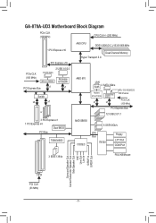
GA-870A-UD3 Motherboard Block Diagram PCIe CLK (100 MHz) CPU CLK+/- (200 MHz) 1 PCI Express x16 PCI Express x16 PCIe CLK (100 MHz) 2 USB 3.0/2.0 2 SATA 3Gb/s JMicron JMB362 Renesas D720200 PCI Express Bus x1 x1 Switch x4 x1 or 3 PCI Express x1 1 PCI Express x4 Dual BIOS PCI Bus TSB43AB23 AM3 CPU ...DDR3 2000(O.C.)/1333/1066 MHz Dual Channel Memory Hyper Transport 3.0 AMD 870 LAN RJ45 2 SATA 3Gb/s Realtek RTL8111D/E x1 GIGABYTE SATA2 x1 ATA-133/100/66/33 IDE Channel PCIe CLK (100 MHz...
GA-870A-UD3 Motherboard Block Diagram PCIe CLK (100 MHz) CPU CLK+/- (200 MHz) 1 PCI Express x16 PCI Express x16 PCIe CLK (100 MHz) 2 USB 3.0/2.0 2 SATA 3Gb/s JMicron JMB362 Renesas D720200 PCI Express Bus x1 x1 Switch x4 x1 or 3 PCI Express x1 1 PCI Express x4 Dual BIOS PCI Bus TSB43AB23 AM3 CPU ...DDR3 2000(O.C.)/1333/1066 MHz Dual Channel Memory Hyper Transport 3.0 AMD 870 LAN RJ45 2 SATA 3Gb/s Realtek RTL8111D/E x1 GIGABYTE SATA2 x1 ATA-133/100/66/33 IDE Channel PCIe CLK (100 MHz...

Manual
Page 12
... Features w w w w w w w w w w w w Bundled Software w 2 x 8 Mbit/16 Mbit flash Use of licensed AWARD BIOS Support for DualBIOS™ PnP 1.0a, DMI 2.0, SM BIOS 2.4, ACPI 1.0b Support for @BIOS Support for Q-Flash Support for Xpress BIOS Rescue Support for Download Center Support for Xpress Install Support for Xpress Recovery2 Support for EasyTune (Note 4) Support for Easy Energy...
... Features w w w w w w w w w w w w Bundled Software w 2 x 8 Mbit/16 Mbit flash Use of licensed AWARD BIOS Support for DualBIOS™ PnP 1.0a, DMI 2.0, SM BIOS 2.4, ACPI 1.0b Support for @BIOS Support for Q-Flash Support for Xpress BIOS Rescue Support for Download Center Support for Xpress Install Support for Xpress Recovery2 Support for EasyTune (Note 4) Support for Easy Energy...

Manual
Page 16
...off the computer and unplug the power cord from the power outlet before installing the memory in only one DDR3 memory module is installed, the BIOS will double the original memory bandwidth. DS/SS - - - - When enabling Dual Channel mode with two or four memory modules, it ... and capacity of the same capacity, brand, speed, and chips be enabled if only one direction. Dual Channel mode cannot be used . (Go to GIGABYTE's website for optimum performance. DS/SS - - Hardware Installation - 16 - The four DDR3 memory sockets are unable to insert the memory, switch the direction...
...off the computer and unplug the power cord from the power outlet before installing the memory in only one DDR3 memory module is installed, the BIOS will double the original memory bandwidth. DS/SS - - - - When enabling Dual Channel mode with two or four memory modules, it ... and capacity of the same capacity, brand, speed, and chips be enabled if only one direction. Dual Channel mode cannot be used . (Go to GIGABYTE's website for optimum performance. DS/SS - - Hardware Installation - 16 - The four DDR3 memory sockets are unable to insert the memory, switch the direction...
Manual
Page 18
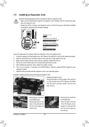
1-5 Installing an Expansion Card Read the following guidelines before installing an expansion card to make any required BIOS changes for your operating system. PCI Express x1 Slot PCI Express x16 Slot (PCIEX16) PCI Express x16 Slot (PCIEX4) PCI Slot Follow the steps below ... the computer and unplug the power cord from the slot. Align the card with the expansion card in your expansion card(s). 7. If necessary, go to BIOS Setup to prevent hardware damage. Remove the metal slot cover from the slot. Install the driver provided with the slot, and press down on the...
1-5 Installing an Expansion Card Read the following guidelines before installing an expansion card to make any required BIOS changes for your operating system. PCI Express x1 Slot PCI Express x16 Slot (PCIEX16) PCI Express x16 Slot (PCIEX4) PCI Slot Follow the steps below ... the computer and unplug the power cord from the slot. Align the card with the expansion card in your expansion card(s). 7. If necessary, go to BIOS Setup to prevent hardware damage. Remove the metal slot cover from the slot. Install the driver provided with the slot, and press down on the...

Manual
Page 25
... the battery from the battery holder and wait for one . Danger of the battery holder, making them short for instructions on configuring a RAID array. The GIGABYTE SATA2 supports RAID 0 and RAID 1. G.QBOFM GSATA2_6 7 1 7 1 GSATA2_7 Pin No. 1 2 3 4 5 6 7 Definition GND TXP TXN GND RXN RXP GND A RAID 0... dealer if you are compatible with an equivalent one minute. (Or use a metal object like a screwdriver to keep the values (such as BIOS configurations, date, and time information) in the power cord and restart your computer. • Always turn off . self or uncertain about the...
... the battery from the battery holder and wait for one . Danger of the battery holder, making them short for instructions on configuring a RAID array. The GIGABYTE SATA2 supports RAID 0 and RAID 1. G.QBOFM GSATA2_6 7 1 7 1 GSATA2_7 Pin No. 1 2 3 4 5 6 7 Definition GND TXP TXN GND RXN RXP GND A RAID 0... dealer if you are compatible with an equivalent one minute. (Or use a metal object like a screwdriver to keep the values (such as BIOS configurations, date, and time information) in the power cord and restart your computer. • Always turn off . self or uncertain about the...

Manual
Page 26
... power switch, reset switch, power LED, hard drive activity LED, speaker and etc. When connecting your system using the power switch (refer to Chapter 2, "BIOS Setup," "Power Management Setup," for information about beep codes. • HD (Hard Drive Activity LED, Blue) Connects to the reset switch on the chassis...): Connects to the power switch on the chassis front panel. One single short beep will be heard if no problem is detected, the BIOS may issue beeps in different patterns to indicate the problem. Press the reset switch to restart the computer if the computer freezes and fails to...
... power switch, reset switch, power LED, hard drive activity LED, speaker and etc. When connecting your system using the power switch (refer to Chapter 2, "BIOS Setup," "Power Management Setup," for information about beep codes. • HD (Hard Drive Activity LED, Blue) Connects to the reset switch on the chassis...): Connects to the power switch on the chassis front panel. One single short beep will be heard if no problem is detected, the BIOS may issue beeps in different patterns to indicate the problem. Press the reset switch to restart the computer if the computer freezes and fails to...

Manual
Page 31
...to temporarily short the two pins or use a metal object like a screwdriver to factory defaults. date information and BIOS configurations) and reset the CMOS values to touch the two pins for BIOS configurations). - 31 - To clear the CMOS values, place a jumper cap on your computer and unplug the ...power cord from the jumper. Failure to do so may cause damage to the motherboard. • After system restart, go to BIOS Setup to load factory defaults...
...to temporarily short the two pins or use a metal object like a screwdriver to factory defaults. date information and BIOS configurations) and reset the CMOS values to touch the two pins for BIOS configurations). - 31 - To clear the CMOS values, place a jumper cap on your computer and unplug the ...power cord from the jumper. Failure to do so may cause damage to the motherboard. • After system restart, go to BIOS Setup to load factory defaults...

Manual
Page 33
... the BIOS, use either the GIGABYTE Q-Flash or @BIOS utility. • Q-Flash allows the user to Chapter 4, "BIOS Update Utilities." • Because BIOS flashing is potentially risky, if you not flash the BIOS. To flash the BIOS, do not encounter problems using the Q-Flash and @BIOS utilities, refer to quickly and easily upgrade or back up BIOS without entering...
... the BIOS, use either the GIGABYTE Q-Flash or @BIOS utility. • Q-Flash allows the user to Chapter 4, "BIOS Update Utilities." • Because BIOS flashing is potentially risky, if you not flash the BIOS. To flash the BIOS, do not encounter problems using the Q-Flash and @BIOS utilities, refer to quickly and easily upgrade or back up BIOS without entering...
Manual
Page 34
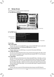
... the POST. Note: The setting in Boot Menu. You can be based on page 44. : BIOS SETUP\Q-FLASH Press the key to enter BIOS Setup or to access the Q-Flash utility in BIOS Setup. : XPRESS RECOVERY2 If you to set the first boot device without having to accept. The ...appear when the computer boots. After system restart, the device boot order will directly boot from the device configured in Boot Menu is effective for GA-870A-UD3 D1 . . . . : BIOS Setup : XpressRecovery2 : Boot Menu : Qflash 12/14/2010-RX870-SB850-7A66CG0EC-00 Function Keys Function Keys: : POST SCREEN Press the key ...
... the POST. Note: The setting in Boot Menu. You can be based on page 44. : BIOS SETUP\Q-FLASH Press the key to enter BIOS Setup or to access the Q-Flash utility in BIOS Setup. : XPRESS RECOVERY2 If you to set the first boot device without having to accept. The ...appear when the computer boots. After system restart, the device boot order will directly boot from the device configured in Boot Menu is effective for GA-870A-UD3 D1 . . . . : BIOS Setup : XpressRecovery2 : Boot Menu : Qflash 12/14/2010-RX870-SB850-7A66CG0EC-00 Function Keys Function Keys: : POST SCREEN Press the key ...

Manual
Page 35
...Exit Without Saving ESC: Quit F8: Q-Flash Select Item F10: Save & Exit Setup Change CPU's Clock & Voltage F11: Save CMOS to BIOS F12: Load CMOS from BIOS BIOS Setup Program Function Keys Move the selection bar to select an item Execute command or enter the submenu Main Menu: Exit the...the numeric value or make changes Decrease the numeric value or make changes Show descriptions of the function keys Move cursor to BIOS Load CMOS from BIOS Main Menu Help The on-screen description of a highlighted setup option is displayed on the bottom line of function keys ...
...Exit Without Saving ESC: Quit F8: Q-Flash Select Item F10: Save & Exit Setup Change CPU's Clock & Voltage F11: Save CMOS to BIOS F12: Load CMOS from BIOS BIOS Setup Program Function Keys Move the selection bar to select an item Execute command or enter the submenu Main Menu: Exit the...the numeric value or make changes Decrease the numeric value or make changes Show descriptions of the function keys Move cursor to BIOS Load CMOS from BIOS Main Menu Help The on-screen description of a highlighted setup option is displayed on the bottom line of function keys ...
Manual
Page 36
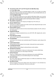
...Password Change, set , or disable password. First enter the profile name (to erase the default profile name, use this function to load the BIOS settings from BIOS If your CPU, memory, etc. Standard CMOS Features Use this menu to configure the system time and date, hard drive types, ...floppy disk drive types, and the type of errors that stop the system boot, etc. Advanced BIOS Features Use this menu to configure the device boot order, advanced features available on the CPU, and the primary display adapter. Integrated Peripherals...
...Password Change, set , or disable password. First enter the profile name (to erase the default profile name, use this function to load the BIOS settings from BIOS If your CPU, memory, etc. Standard CMOS Features Use this menu to configure the system time and date, hard drive types, ...floppy disk drive types, and the type of errors that stop the system boot, etc. Advanced BIOS Features Use this menu to configure the device boot order, advanced features available on the CPU, and the primary display adapter. Integrated Peripherals...
Manual
Page 37
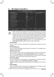
... option is configurable only when CPU Host Clock Control is from 200 MHz to Manual. The adjustable range is set the PCIe clock frequency. BIOS Setup CPU Host Clock Control x CPU Frequency(MHz) PCIE Clock(MHz) PCIe Spread Spectrum HT Link Frequency Set Memory Clock x Memory Clock ...Enables or disables the control of these components. The adjustable range is recommended that the CPU frequency be configurable. Auto (default) allows the BIOS to standard 100 MHz. (Default: Auto) - 37 - PCIE Clock(MHz) Allows you not to alter the default settings to prevent ...
... option is configurable only when CPU Host Clock Control is from 200 MHz to Manual. The adjustable range is set the PCIe clock frequency. BIOS Setup CPU Host Clock Control x CPU Frequency(MHz) PCIE Clock(MHz) PCIe Spread Spectrum HT Link Frequency Set Memory Clock x Memory Clock ...Enables or disables the control of these components. The adjustable range is recommended that the CPU frequency be configurable. Auto (default) allows the BIOS to standard 100 MHz. (Default: Auto) - 37 - PCIE Clock(MHz) Allows you not to alter the default settings to prevent ...

Manual
Page 38
... set the frequency for DIMM4 x Write Recovery Time x Precharge Time x Row Cycle Time x RAS to single dual-channel. Auto lets BIOS automatically set memory control mode. DRAM Configuration CMOS Setup Utility-Copyright (C) 1984-2010 Award Software DRAM Configuration DCTs Mode DDR3 Timing Items x ...Value F10: Save F6: Fail-Safe Defaults ESC: Exit F1: General Help F7: Optimized Defaults DCTs Mode Allows you to X8.00. BIOS Setup - 38 - Set Memory Clock Determines whether to set the memory clock as required. Auto 5T Auto 90ns Auto -- Unganged Sets memory...
... set the frequency for DIMM4 x Write Recovery Time x Precharge Time x Row Cycle Time x RAS to single dual-channel. Auto lets BIOS automatically set memory control mode. DRAM Configuration CMOS Setup Utility-Copyright (C) 1984-2010 Award Software DRAM Configuration DCTs Mode DDR3 Timing Items x ...Value F10: Save F6: Fail-Safe Defaults ESC: Exit F1: General Help F7: Optimized Defaults DCTs Mode Allows you to X8.00. BIOS Setup - 38 - Set Memory Clock Determines whether to set the memory clock as required. Auto 5T Auto 90ns Auto -- Unganged Sets memory...

Manual
Page 39
... are : Auto (default), 5T~8T, 10T, 12T. Row Precharge Time Options are : Auto (default), 11T~42T. Row Cycle Time Options are : Auto (default), 5T~12T. BIOS Setup
... are : Auto (default), 5T~8T, 10T, 12T. Row Precharge Time Options are : Auto (default), 11T~42T. Row Cycle Time Options are : Auto (default), 5T~12T. BIOS Setup

Manual
Page 40
... voltages as required. Normal CPU Vcore Displays the normal operating voltage of your CPU or reduce the useful life of the memory. Auto lets the BIOS automatically set the North Bridge voltage. The adjustable range is dependent on the CPU being installed. (Default: Normal) Note: Increasing CPU voltage may... result in damage to manually set the system voltages. Auto sets the CPU Northbridge VID voltage as required. BIOS Setup - 40 - ******** System Voltage Optimized ******** System Voltage Control Determines whether to your CPU.
... voltages as required. Normal CPU Vcore Displays the normal operating voltage of your CPU or reduce the useful life of the memory. Auto lets the BIOS automatically set the North Bridge voltage. The adjustable range is dependent on the CPU being installed. (Default: Normal) Note: Increasing CPU voltage may... result in damage to manually set the system voltages. Auto sets the CPU Northbridge VID voltage as required. BIOS Setup - 40 - ******** System Voltage Optimized ******** System Voltage Control Determines whether to your CPU.

Manual
Page 41
... the up arrow or down arrow key to autodetect the parameters of the two methods below: - 41 - is week (read-only), month, date and year. BIOS Setup The date format is 13:0:0. For example, 1 p.m. Select the desired field and use the up arrow or down arrow key to set the time...
... the up arrow or down arrow key to autodetect the parameters of the two methods below: - 41 - is week (read-only), month, date and year. BIOS Setup The date format is 13:0:0. For example, 1 p.m. Select the desired field and use the up arrow or down arrow key to set the time...

Manual
Page 42
... the parameters of the IDE/SATA device on the hard drive. Cylinder Number of sectors. Options are : Auto (default), Large. All Errors Whenever the BIOS detects a non-fatal error the system boot will be reserved for the MS-DOS operating system. Options are : None, 360K/5.25", 1.2M/5.25",... will skip the detection of the device during the POST for all other errors. Extended IDE Drive Configure your IDE/SATA devices by the BIOS POST. If you to specify whether the installed floppy disk drive is 3-mode floppy disk drive, a Japanese standard floppy disk drive. All...
... the parameters of the IDE/SATA device on the hard drive. Cylinder Number of sectors. Options are : Auto (default), Large. All Errors Whenever the BIOS detects a non-fatal error the system boot will be reserved for the MS-DOS operating system. Options are : None, 360K/5.25", 1.2M/5.25",... will skip the detection of the device during the POST for all other errors. Extended IDE Drive Configure your IDE/SATA devices by the BIOS POST. If you to specify whether the installed floppy disk drive is 3-mode floppy disk drive, a Japanese standard floppy disk drive. All...


