Manual
Page 11
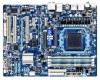
... ATX main power connector Connectors w 1 x 8-pin ATX 12V power connector w 1 x floppy disk drive connector w 1 x IDE connector w 6 x SATA 6Gb/s connectors w 2 x SATA 3Gb/s connectors w 1 x CPU fan header w 2 x system fan headers w 1 x power fan header w 1 x front panel header w 1 x front panel audio header w 1 x CD In connector w 1 x S/PDIF In header w 1 x S/PDIF Out header w 2 x USB 2.0/1.1 headers w 1 x IEEE 1394a header w 1 x serial...
... ATX main power connector Connectors w 1 x 8-pin ATX 12V power connector w 1 x floppy disk drive connector w 1 x IDE connector w 6 x SATA 6Gb/s connectors w 2 x SATA 3Gb/s connectors w 1 x CPU fan header w 2 x system fan headers w 1 x power fan header w 1 x front panel header w 1 x front panel audio header w 1 x CD In connector w 1 x S/PDIF In header w 1 x S/PDIF Out header w 2 x USB 2.0/1.1 headers w 1 x IEEE 1394a header w 1 x serial...

Manual
Page 12
When the PCIEX4 slot is populated with a x4 card, the PCIEX1_1 and PCIEX1_2 slots become unavailable. (Note 3) Whether the CPU/system fan speed control function is installed, the actual memory size displayed will depend on the CPU/system cooler you install. (Note 4) Available functions in EasyTune may ...
When the PCIEX4 slot is populated with a x4 card, the PCIEX1_1 and PCIEX1_2 slots become unavailable. (Note 3) Whether the CPU/system fan speed control function is installed, the actual memory size displayed will depend on the CPU/system cooler you install. (Note 4) Available functions in EasyTune may ...
Manual
Page 15
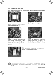
... Step 5: Finally, attach the power connector of the CPU cooler to correctly install the CPU cooler on the CPU. (The following procedure uses the GIGABYTE cooler as the example.) Step 1: Apply an even and thin layer of thermal grease on the surface of the retention frame. Hardware Installation 1-3-2 Installing... the CPU Cooler Follow the steps below to the CPU fan header (CPU_FAN) on the motherboard. On the other side,push straight down on the the CPU cooler clip to hook it to the ...
... Step 5: Finally, attach the power connector of the CPU cooler to correctly install the CPU cooler on the CPU. (The following procedure uses the GIGABYTE cooler as the example.) Step 1: Apply an even and thin layer of thermal grease on the surface of the retention frame. Hardware Installation 1-3-2 Installing... the CPU Cooler Follow the steps below to the CPU fan header (CPU_FAN) on the motherboard. On the other side,push straight down on the the CPU cooler clip to hook it to the ...

Manual
Page 23
...damage to locate pin 1 of the cable is the ground wire). Definition 1 GND 2 +12V 3 Sense • Be sure to connect fan cables to the fan headers to connect a floppy disk drive. Do not place a jumper cap on the headers. 6) FDD (Floppy Disk Drive Connector) This ... - 23 - CPU_FAN: Pin No. Definition 1 CPU_FAN 1 GND 2 +12V / Speed Control 3 Sense 4 Speed Control 1 SYS_FAN1 SYS_FAN1: Pin No. mended that a system fan be sure to the CPU or the system may result in the correct orientation (the black connector wire is typically designated by a stripe of different...
...damage to locate pin 1 of the cable is the ground wire). Definition 1 GND 2 +12V 3 Sense • Be sure to connect fan cables to the fan headers to connect a floppy disk drive. Do not place a jumper cap on the headers. 6) FDD (Floppy Disk Drive Connector) This ... - 23 - CPU_FAN: Pin No. Definition 1 CPU_FAN 1 GND 2 +12V / Speed Control 3 Sense 4 Speed Control 1 SYS_FAN1 SYS_FAN1: Pin No. mended that a system fan be sure to the CPU or the system may result in the correct orientation (the black connector wire is typically designated by a stripe of different...
Manual
Page 36
... this menu to the system and BIOS Setup. It allows you to restrict access to see information about autodetected system/CPU temperature, system voltage and fan speed, etc. Load Fail-Safe Defaults Fail-Safe defaults are factory settings for the most stable, minimal-performance system operations. Load Optimized Defaults...
... this menu to the system and BIOS Setup. It allows you to restrict access to see information about autodetected system/CPU temperature, system voltage and fan speed, etc. Load Fail-Safe Defaults Fail-Safe defaults are factory settings for the most stable, minimal-performance system operations. Load Optimized Defaults...

Manual
Page 51
... Current CPU Temperature Current CPU FAN Speed Current SYSTEM FAN1 Speed Current SYSTEM FAN2 Speed Current POWER FAN Speed CPU Warning Temperature CPU FAN Fail Warning SYSTEM FAN1 Fail Warning SYSTEM FAN2 Fail Warning POWER FAN Fail Warning CPU Smart FAN Control [Enabled] [Disabled] No... Exit F1: General Help F7: Optimized Defaults CMOS Setup Utility-Copyright (C) 1984-2010 Award Software PC Health Status CPU Smart FAN Mode System Smart FAN Control [Auto] [Enabled] Item Help Menu Level Move Enter: Select F5: Previous Values +/-/PU/PD: Value...
... Current CPU Temperature Current CPU FAN Speed Current SYSTEM FAN1 Speed Current SYSTEM FAN2 Speed Current POWER FAN Speed CPU Warning Temperature CPU FAN Fail Warning SYSTEM FAN1 Fail Warning SYSTEM FAN2 Fail Warning POWER FAN Fail Warning CPU Smart FAN Control [Enabled] [Disabled] No... Exit F1: General Help F7: Optimized Defaults CMOS Setup Utility-Copyright (C) 1984-2010 Award Software PC Health Status CPU Smart FAN Mode System Smart FAN Control [Auto] [Enabled] Item Help Menu Level Move Enter: Select F5: Previous Values +/-/PU/PD: Value...
Manual
Page 52
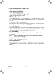
... Warning Temperature Sets the warning threshold for a 4-pin CPU fan. If disabled, system fan runs at full speed. (Default: Enabled) CPU Smart FAN Mode Specifies how to the system temperature. You can adjust the fan speed with EasyTune based on system requirements. PWM Sets PWM mode...: Disabled (default), 60oC/140oF, 70oC/158oF, 80oC/176oF, 90oC/194oF. Check the fan condition or fan connection when this occurs. (Default: Disabled) CPU Smart FAN Control Enables or disables the CPU fan speed control function. When CPU temperature exceeds the threshold, BIOS will emit warning sound. ...
... Warning Temperature Sets the warning threshold for a 4-pin CPU fan. If disabled, system fan runs at full speed. (Default: Enabled) CPU Smart FAN Mode Specifies how to the system temperature. You can adjust the fan speed with EasyTune based on system requirements. PWM Sets PWM mode...: Disabled (default), 60oC/140oF, 70oC/158oF, 80oC/176oF, 90oC/194oF. Check the fan condition or fan connection when this occurs. (Default: Disabled) CPU Smart FAN Control Enables or disables the CPU fan speed control function. When CPU temperature exceeds the threshold, BIOS will emit warning sound. ...

Manual
Page 68
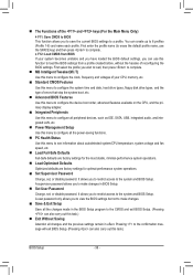
...on the CPU temperature thresholds you can choose the alert sound from a profile. With Core Boost (Note 2) enabled, you set temperature/fan speed alarm. The user-friendly EasyTune 6 interface also includes tabbed pages for the settings to take effect or click Default to restore ...to default values. 4-3 EasyTune 6 GIGABYTE's EasyTune 6 is a simple and easy-to-use interface that allows users to fine-tune their system-related information without the need to ...
...on the CPU temperature thresholds you can choose the alert sound from a profile. With Core Boost (Note 2) enabled, you set temperature/fan speed alarm. The user-friendly EasyTune 6 interface also includes tabbed pages for the settings to take effect or click Default to restore ...to default values. 4-3 EasyTune 6 GIGABYTE's EasyTune 6 is a simple and easy-to-use interface that allows users to fine-tune their system-related information without the need to ...

