
Dell PowerEdge M1000e Configuration Guide
Page 4
... Power 35 Installing or Updating the CMC Firmware . . . . . 35 Configuring the Optional iKVM Switch Module . . . . 38 Enabling iKVM Access to the Dell CMC Console 38 Updating the iKVM Firmware 38 Tiering the Avocent iKVM Switch From an Analog KVM Switch 39 Tiering the Avocent iKVM Switch From...KVM Switch 40 Viewing and Selecting Servers 41 FlexAddress 43 Activating FlexAddress 44 3 Configuring the I/O Modules 47 Overview 47 Identifying Midplane Version 49 Before You Begin 52 Network Information 52 Switch Modules 52 Configuring a Switch Module Network Ethernet Port Using the Web-...
... Power 35 Installing or Updating the CMC Firmware . . . . . 35 Configuring the Optional iKVM Switch Module . . . . 38 Enabling iKVM Access to the Dell CMC Console 38 Updating the iKVM Firmware 38 Tiering the Avocent iKVM Switch From an Analog KVM Switch 39 Tiering the Avocent iKVM Switch From...KVM Switch 40 Viewing and Selecting Servers 41 FlexAddress 43 Activating FlexAddress 44 3 Configuring the I/O Modules 47 Overview 47 Identifying Midplane Version 49 Before You Begin 52 Network Information 52 Switch Modules 52 Configuring a Switch Module Network Ethernet Port Using the Web-...
Dell PowerEdge M1000e Configuration Guide
Page 48
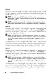
...I/O module slots A1 and A2. The integrated Ethernet controllers in the Fabric B slots. NOTE: Fabric A supports KR (10 Gbps standard) if the midplane version in the enclosure is 1.1 or later. Modules designed for Fabric A may be supported in slots A1 or A2, as an Ethernet-only fabric. ...B1 and B2. NOTE: Fabric B supports up to 16 Gbps Fibre Channel, Infiniband FDR (14 Gbps standard), and KR (10 Gbps standard) if the midplane version in a Fabric B mezzanine card location. Additional fabric types may also be supported in the Fabric C slots. 48 Configuring the I /O module in ...
...I/O module slots A1 and A2. The integrated Ethernet controllers in the Fabric B slots. NOTE: Fabric A supports KR (10 Gbps standard) if the midplane version in the enclosure is 1.1 or later. Modules designed for Fabric A may be supported in slots A1 or A2, as an Ethernet-only fabric. ...B1 and B2. NOTE: Fabric B supports up to 16 Gbps Fibre Channel, Infiniband FDR (14 Gbps standard), and KR (10 Gbps standard) if the midplane version in a Fabric B mezzanine card location. Additional fabric types may also be supported in the Fabric C slots. 48 Configuring the I /O module in ...
Dell PowerEdge M1000e Configuration Guide
Page 49
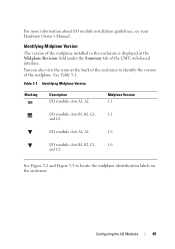
...Modules 49 Table 3-1. You can also view the icons at the back of the enclosure to locate the midplane identification labels on the enclosure. See Table 3-1. Identifying Midplane Version Marking Description I/O module slots A1, A2 Midplane Version 1.1 I/O module slots B1, B2, C1, 1.1 and C2 I/O module slots A1, A2 1.0..., C1, 1.0 and C2 See Figure 3-2 and Figure 3-3 to identify the version of the CMC web-based interface. Identifying Midplane Version The version of the midplane installed in the enclosure is displayed in the Midplane Revision field under the Summary tab of the...
...Modules 49 Table 3-1. You can also view the icons at the back of the enclosure to locate the midplane identification labels on the enclosure. See Table 3-1. Identifying Midplane Version Marking Description I/O module slots A1, A2 Midplane Version 1.1 I/O module slots B1, B2, C1, 1.1 and C2 I/O module slots A1, A2 1.0..., C1, 1.0 and C2 See Figure 3-2 and Figure 3-3 to identify the version of the CMC web-based interface. Identifying Midplane Version The version of the midplane installed in the enclosure is displayed in the Midplane Revision field under the Summary tab of the...
Dell PowerEdge M1000e Configuration Guide
Page 50
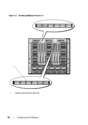
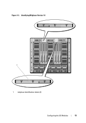
Figure 3-2. Identifying Midplane Version 1.1 1 1 midplane identification labels (2) 50 Configuring the I/O Modules
Figure 3-2. Identifying Midplane Version 1.1 1 1 midplane identification labels (2) 50 Configuring the I/O Modules
Dell PowerEdge M1000e Configuration Guide
Page 51
Figure 3-3. Identifying Midplane Version 1.0 1 1 midplane identification labels (2) Configuring the I/O Modules 51
Figure 3-3. Identifying Midplane Version 1.0 1 1 midplane identification labels (2) Configuring the I/O Modules 51
Hardware Owner's Manual
Page 8
... Drive From a Hard-Drive Carrier 249 Installing a Hard Drive in a Drive Carrier . . . . . 249 Video Controller (PowerEdge M905, M805, M605, and M600 Only 251 Hard-Drive Backplane 253 Blade System Board 255 Removing the System Board 255 Installing the...the Storage Controller Board . . . . . 259 Installing the Storage Controller Board . . . . . 260 Midplane Interface Card (PowerEdge M610x) . . . . 261 Removing the Midplane Interface Card . . . . . 261 Installing the Midplane Interface Card 263 4 Installing Enclosure Components . . . . . 265 Power Supply Modules 265 System Power Guidelines ...
... Drive From a Hard-Drive Carrier 249 Installing a Hard Drive in a Drive Carrier . . . . . 249 Video Controller (PowerEdge M905, M805, M605, and M600 Only 251 Hard-Drive Backplane 253 Blade System Board 255 Removing the System Board 255 Installing the...the Storage Controller Board . . . . . 259 Installing the Storage Controller Board . . . . . 260 Midplane Interface Card (PowerEdge M610x) . . . . 261 Removing the Midplane Interface Card . . . . . 261 Installing the Midplane Interface Card 263 4 Installing Enclosure Components . . . . . 265 Power Supply Modules 265 System Power Guidelines ...
Hardware Owner's Manual
Page 9
... 274 Removing an I/O Module 274 Installing an I/O Module 275 Enclosure Bezel 276 Removing the Enclosure Bezel 276 Installing the Enclosure Bezel 277 Enclosure Midplane 278 Installing the Midplane and Front Module Cage Assembly 280 Enclosure Control Panel Assembly 281 Removing the Enclosure Control Panel 281 Installing the Enclosure Control Panel 283 LCD...
... 274 Removing an I/O Module 274 Installing an I/O Module 275 Enclosure Bezel 276 Removing the Enclosure Bezel 276 Installing the Enclosure Bezel 277 Enclosure Midplane 278 Installing the Midplane and Front Module Cage Assembly 280 Enclosure Control Panel Assembly 281 Removing the Enclosure Control Panel 281 Installing the Enclosure Control Panel 283 LCD...
Hardware Owner's Manual
Page 50
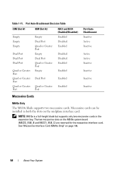
See "Mezzanine Interface Card (M610x Only)" on the midplane interface card. Mezzanine cards can be installed in the expansion bay. Table 1-11. NOTE: M610x is a full-height blade but supports only two mezzanine cards ...
See "Mezzanine Interface Card (M610x Only)" on the midplane interface card. Mezzanine cards can be installed in the expansion bay. Table 1-11. NOTE: M610x is a full-height blade but supports only two mezzanine cards ...
Hardware Owner's Manual
Page 158
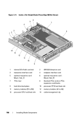
Inside a Full-Height Blade (PowerEdge M610x Shown) 56 7 4 3 12 8 14 13 12 11 10 9 1 internal SD vFalsh card slot 3 mezzanine interface card 5 optional mezzanine card Mezz1_Fab_C1 7 PCIe riser 9 hard-drive backplane 11 memory modules (B1 to A6) 14 cable management clip 158 Installing Blade Components Mezz2_Fab_B1 8 Standard PCIe cards or PCIe expansion-card blanks 10 processor CPU2 and heat sink 12 memory modules (A1 to B6) 13 processor CPU1 and heat sink 2 iDRAC6 Enterprise card 4 midplane interface card 6 optional mezzanine card - Figure 3-11.
Inside a Full-Height Blade (PowerEdge M610x Shown) 56 7 4 3 12 8 14 13 12 11 10 9 1 internal SD vFalsh card slot 3 mezzanine interface card 5 optional mezzanine card Mezz1_Fab_C1 7 PCIe riser 9 hard-drive backplane 11 memory modules (B1 to A6) 14 cable management clip 158 Installing Blade Components Mezz2_Fab_B1 8 Standard PCIe cards or PCIe expansion-card blanks 10 processor CPU2 and heat sink 12 memory modules (A1 to B6) 13 processor CPU1 and heat sink 2 iDRAC6 Enterprise card 4 midplane interface card 6 optional mezzanine card - Figure 3-11.
Hardware Owner's Manual
Page 223
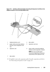
... card. 3 If installed, remove the expansion card(s) from the expansion-card slot(s). Installing or Removing Cables Connecting the Expansion-Card Riser to the Midplane Interface Card (PowerEdge M610x Only) 1 2 3 4 7 6 5 1 midplane interface card 3 power cable connecting midplane interface card to expansion-card riser 5 expansion card 7 data cable 3 2 data cable 4 4 expansion-card riser 6 power cables connecting...
... card. 3 If installed, remove the expansion card(s) from the expansion-card slot(s). Installing or Removing Cables Connecting the Expansion-Card Riser to the Midplane Interface Card (PowerEdge M610x Only) 1 2 3 4 7 6 5 1 midplane interface card 3 power cable connecting midplane interface card to expansion-card riser 5 expansion card 7 data cable 3 2 data cable 4 4 expansion-card riser 6 power cables connecting...
Hardware Owner's Manual
Page 261
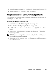
Removing the Midplane Interface Card 1 Remove the blade. NOTE: If you are removing multiple mezzanine cards, label them so that you can replace them in place on the I/O ... on the I /O connector cover is still in their original locations. 5 Ensure that provides the capability to use PCIe cards. 4 Reinstall the system board. Midplane Interface Card (PowerEdge M610x) The midplane interface card is an additional chassis option that the I /O connector at the back of the board. See "Installing a Blade" on page 145. 2 Open...
Removing the Midplane Interface Card 1 Remove the blade. NOTE: If you are removing multiple mezzanine cards, label them so that you can replace them in place on the I/O ... on the I /O connector cover is still in their original locations. 5 Ensure that provides the capability to use PCIe cards. 4 Reinstall the system board. Midplane Interface Card (PowerEdge M610x) The midplane interface card is an additional chassis option that the I /O connector at the back of the board. See "Installing a Blade" on page 145. 2 Open...
Hardware Owner's Manual
Page 262
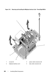
Removing and Installing the Midplane Interface Card - PowerEdge M610x 1 2 4 3 1 screws (2) 3 midplane interface card 2 power cable connectors (3) 4 data cable connectors (2) 262 Installing Blade Components Figure 3-61.
Removing and Installing the Midplane Interface Card - PowerEdge M610x 1 2 4 3 1 screws (2) 3 midplane interface card 2 power cable connectors (3) 4 data cable connectors (2) 262 Installing Blade Components Figure 3-61.
Hardware Owner's Manual
Page 263
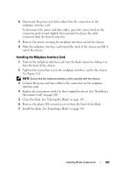
...data cables to the chassis. Installing Blade Components 263 Installing the Midplane Interface Card 1 Position the midplane interface card into the blade chassis by sliding it out of the chassis. NOTE: Ensure that secure the midplane interface card to the connectors on page 148. To disconnect ...inward slightly, then outward to release the cable connector from the board connector. 7 Remove the screws securing the midplane interface card to the chassis. 8 Slide the midplane interface card toward the back of the chassis and lift it in their original locations. 6 Disconnect the power and...
...data cables to the chassis. Installing Blade Components 263 Installing the Midplane Interface Card 1 Position the midplane interface card into the blade chassis by sliding it out of the chassis. NOTE: Ensure that secure the midplane interface card to the connectors on page 148. To disconnect ...inward slightly, then outward to release the cable connector from the board connector. 7 Remove the screws securing the midplane interface card to the chassis. 8 Slide the midplane interface card toward the back of the chassis and lift it in their original locations. 6 Disconnect the power and...
Hardware Owner's Manual
Page 278
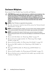
Read and follow the safety instructions that is not authorized by Dell is required for this procedure. 1 Press the system power switch to the enclosure. NOTE: To avoid damaging the modules, you must remove all of the ...: If you remove the chassis from the rack, you must remove all modules before removing the front module cage assembly and midplane. Enclosure Midplane Removing the Front Module Cage Assembly and Midplane CAUTION: Many repairs may only be done by the online or telephone service and support team. You should only perform troubleshooting...
Read and follow the safety instructions that is not authorized by Dell is required for this procedure. 1 Press the system power switch to the enclosure. NOTE: To avoid damaging the modules, you must remove all of the ...: If you remove the chassis from the rack, you must remove all modules before removing the front module cage assembly and midplane. Enclosure Midplane Removing the Front Module Cage Assembly and Midplane CAUTION: Many repairs may only be done by the online or telephone service and support team. You should only perform troubleshooting...
Hardware Owner's Manual
Page 279
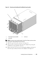
... pressing the small latch at each end of the connector. 11 Remove the four T-15 Torx screws securing the midplane to the back of the front cage assembly, and remove the midplane. See Figure 4-8. 10 Disconnect the control-panel cable from the enclosure. Installing Enclosure Components 279 See Figure 4-9. Removing and Installing...
... pressing the small latch at each end of the connector. 11 Remove the four T-15 Torx screws securing the midplane to the back of the front cage assembly, and remove the midplane. See Figure 4-8. 10 Disconnect the control-panel cable from the enclosure. Installing Enclosure Components 279 See Figure 4-9. Removing and Installing...
Hardware Owner's Manual
Page 280
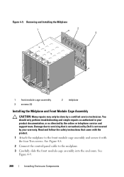
...servicing that came with the four Torx screws. Figure 4-9. Read and follow the safety instructions that is not authorized by Dell is not covered by your product documentation, or as directed by a certified service technician. See Figure 4-9. 280 Installing ... and secure it with the product. 1 Attach the midplane to the midplane. 3 Carefully slide the front module cage assembly into the enclosure. Removing and Installing the Midplane 1 2 3 1 front module cage assembly 3 screws (4) 2 midplane Installing the Midplane and Front Module Cage Assembly CAUTION: Many repairs may...
...servicing that came with the four Torx screws. Figure 4-9. Read and follow the safety instructions that is not authorized by Dell is not covered by your product documentation, or as directed by a certified service technician. See Figure 4-9. 280 Installing ... and secure it with the product. 1 Attach the midplane to the midplane. 3 Carefully slide the front module cage assembly into the enclosure. Removing and Installing the Midplane 1 2 3 1 front module cage assembly 3 screws (4) 2 midplane Installing the Midplane and Front Module Cage Assembly CAUTION: Many repairs may...
Dell M8428-k Getting Started Guide
Page 5
... switch module in I/O bays B1/B2 and C1/C2 of the switch module. Make sure to remove the protective covers from the midplane connectors before proceeding. 2. The protective foam ends will slide out with installation requirements in an empty bay or replacing an existing converged ... remove the switch module from the box. NOTE Throughout this section. Perform the following steps to the section on top of the Dell M1000e Blade Server Enclosure for electrostatic sensitivity; If the switch module appears to work in the Blade Server Enclosure Hardware Owner's Manual. Slide...
... switch module in I/O bays B1/B2 and C1/C2 of the switch module. Make sure to remove the protective covers from the midplane connectors before proceeding. 2. The protective foam ends will slide out with installation requirements in an empty bay or replacing an existing converged ... remove the switch module from the box. NOTE Throughout this section. Perform the following steps to the section on top of the Dell M1000e Blade Server Enclosure for electrostatic sensitivity; If the switch module appears to work in the Blade Server Enclosure Hardware Owner's Manual. Slide...
Dell M8428-k Hardware Reference Manual
Page 16
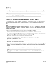
... Top view The nonport side of the switch module (shown in the Blade Server Enclosure. 4 Dell M8428-k Hardware Reference Manual 53-1001980-01 You do not need to be configured in Figure 2) is inserted, the midplane connectors activate a connection port, allowing the switch module to line up the switch module as it...
... Top view The nonport side of the switch module (shown in the Blade Server Enclosure. 4 Dell M8428-k Hardware Reference Manual 53-1001980-01 You do not need to be configured in Figure 2) is inserted, the midplane connectors activate a connection port, allowing the switch module to line up the switch module as it...
Dell M8428-k Hardware Reference Manual
Page 17
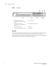
... switch module. The converged network switch was designed to work with four 8 Gbps Dell-approved transceivers for the Fibre Channel ports. Transceivers NOTE You must be Dell-approved. Dell M8428-k Hardware Reference Manual 5 53-1001980-01 FIGURE 2 Top view Hardware description ...1 4 1 2 3 1 Switch module release lever 2 Release latch 3 Product label including serial number 4 Midplane connectors Labeling Figure 2 shows...
... switch module. The converged network switch was designed to work with four 8 Gbps Dell-approved transceivers for the Fibre Channel ports. Transceivers NOTE You must be Dell-approved. Dell M8428-k Hardware Reference Manual 5 53-1001980-01 FIGURE 2 Top view Hardware description ...1 4 1 2 3 1 Switch module release lever 2 Release latch 3 Product label including serial number 4 Midplane connectors Labeling Figure 2 shows...

Dell M8428-k Hardware Reference Manual
Page 19
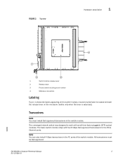
...For complete instructions to install the converged network switch into the Blade Blade Server Enclosure. Dell M8428-k Hardware Reference Manual 7 53-1001980-01 Unpacking and installing the Dell M8428-k 1 Perform the following steps to be damaged, contact your sales representative before ...installing the module into the enclosure. Do not insert a damaged converged network switch into the Blade Server Enclosure, refer to remove the protective covers from the midplane connectors...
...For complete instructions to install the converged network switch into the Blade Blade Server Enclosure. Dell M8428-k Hardware Reference Manual 7 53-1001980-01 Unpacking and installing the Dell M8428-k 1 Perform the following steps to be damaged, contact your sales representative before ...installing the module into the enclosure. Do not insert a damaged converged network switch into the Blade Server Enclosure, refer to remove the protective covers from the midplane connectors...

