

Glossary
Page 1
...data or instructions for developing technology standards in the U.S. BTU - CIM - Centimeter(s). 1 blade - British thermal unit. bus - The primary organization for quick data retrieval. The modules are mounted into a chassis that contains a processor, memory, and a hard drive. CA - bootable media - Your... ACPI - A fast storage area that allows the processor to communicate with MIB data from the hard drive. C - Dell™ Glossary NOTE: For additional information on storage terminology, visit the Storage Networking Industry Association's website at www.snia.org...
...data or instructions for developing technology standards in the U.S. BTU - CIM - Centimeter(s). 1 blade - British thermal unit. bus - The primary organization for quick data retrieval. The modules are mounted into a chassis that contains a processor, memory, and a hard drive. CA - bootable media - Your... ACPI - A fast storage area that allows the processor to communicate with MIB data from the hard drive. C - Dell™ Glossary NOTE: For additional information on storage terminology, visit the Storage Networking Industry Association's website at www.snia.org...

Information Update
Page 5
NOTE: For a detailed mapping of each PowerEdge system, see the document Quadport Capable Hardware For the M1000e Modular Chassis on support.dell.com/manuals. PowerEdge Blades - Table 1-1. I/O Module Port Assignments-Half-Height Blades Blade n A1 Integrated LOM1 Port n Integrated LOM2 Mezz_FAB_B_Blade n_Port1 Mezz_FAB_B_Blade n_Port2 Mezz_FAB_B_Blade n_Port3 Mezz_FAB_B_Blade n_Port4 Mezz_FAB_C_Blade n_Port1 Mezz_FAB_C_Blade n_Port2 Mezz_FAB_C_Blade n_Port3 Mezz_FAB_C_Blade n_Port4 I /O module port mapping...
NOTE: For a detailed mapping of each PowerEdge system, see the document Quadport Capable Hardware For the M1000e Modular Chassis on support.dell.com/manuals. PowerEdge Blades - Table 1-1. I/O Module Port Assignments-Half-Height Blades Blade n A1 Integrated LOM1 Port n Integrated LOM2 Mezz_FAB_B_Blade n_Port1 Mezz_FAB_B_Blade n_Port2 Mezz_FAB_B_Blade n_Port3 Mezz_FAB_B_Blade n_Port4 Mezz_FAB_C_Blade n_Port1 Mezz_FAB_C_Blade n_Port2 Mezz_FAB_C_Blade n_Port3 Mezz_FAB_C_Blade n_Port4 I /O module port mapping...
Information Update
Page 6
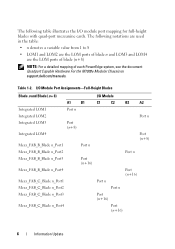
... LOM3 and LOM4 are the LOM ports of blade (n+8) NOTE: For a detailed mapping of each PowerEdge system, see the document Quadport Capable Hardware For the M1000e Modular Chassis on support.dell.com/manuals. I/O Module Port Assignments-Full-Height Blades Blade n and Blade (n + 8) I /O module port mapping for full-height blades with quad-port mezzanine cards. The following table illustrates the...
... LOM3 and LOM4 are the LOM ports of blade (n+8) NOTE: For a detailed mapping of each PowerEdge system, see the document Quadport Capable Hardware For the M1000e Modular Chassis on support.dell.com/manuals. I/O Module Port Assignments-Full-Height Blades Blade n and Blade (n + 8) I /O module port mapping for full-height blades with quad-port mezzanine cards. The following table illustrates the...
Information Update
Page 11
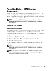
... update the CMC firmware to the latest revision. NOTE: See the latest Dell Chassis Management Controller User's Guide at support.dell.com for complete instructions on . Information Update 11 PowerEdge Blades - NOTE: The firmware update, by default, will not power on how...M1000e enclosure with your local system. The following software components are included with an older CMC firmware version, the new blades will retain the current CMC settings. CMC Firmware Requirements PowerEdge M905 and M805 blades require CMC firmware version 1.2 or later. NOTE: See the latest Dell Chassis...
... update the CMC firmware to the latest revision. NOTE: See the latest Dell Chassis Management Controller User's Guide at support.dell.com for complete instructions on . Information Update 11 PowerEdge Blades - NOTE: The firmware update, by default, will not power on how...M1000e enclosure with your local system. The following software components are included with an older CMC firmware version, the new blades will retain the current CMC settings. CMC Firmware Requirements PowerEdge M905 and M805 blades require CMC firmware version 1.2 or later. NOTE: See the latest Dell Chassis...
Information Update
Page 13
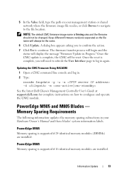
... to log in Progress." PowerEdge M905 and M805 Blades - Memory Sparing Requirements The following information updates the memory sparing subsections in . 2 Type: racadm fwupdate -g -u -a -d -m See the latest Dell Chassis Management Controller User's Guide at support.dell.com for complete instructions on... your Hardware Owner's Manual and these blades' system information labels. NOTE: The default CMC firmware image name is complete,...
... to log in Progress." PowerEdge M905 and M805 Blades - Memory Sparing Requirements The following information updates the memory sparing subsections in . 2 Type: racadm fwupdate -g -u -a -d -m See the latest Dell Chassis Management Controller User's Guide at support.dell.com for complete instructions on... your Hardware Owner's Manual and these blades' system information labels. NOTE: The default CMC firmware image name is complete,...
Rack Installation Guide
Page 20
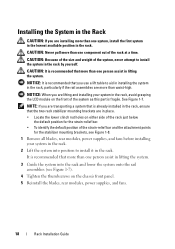
... modules, power supplies, and fans before installing your system in the rack, avoid grasping the LCD module on the chassis front panel. 5 Reinstall the blades, rear modules, power supplies, and fans. 18 Rack Installation Guide See Figure 1-7. NOTICE: When you are lifting and installing your system in the rack. 2 Lift ...
... modules, power supplies, and fans before installing your system in the rack, avoid grasping the LCD module on the chassis front panel. 5 Reinstall the blades, rear modules, power supplies, and fans. 18 Rack Installation Guide See Figure 1-7. NOTICE: When you are lifting and installing your system in the rack. 2 Lift ...
Dell PowerEdge M1000e Configuration Guide
Page 7
... bays in the enclosure. About Your System 7 The power supplies, fans, CMC, optional iKVM module, and I /O module for external network connectivity. To function as a system, a blade is inserted into a Dell PowerEdge M1000e enclosure (chassis) that supports power supplies, fan modules, a Chassis Management Controller (CMC) module, and at all times with either a module or with a blank.
... bays in the enclosure. About Your System 7 The power supplies, fans, CMC, optional iKVM module, and I /O module for external network connectivity. To function as a system, a blade is inserted into a Dell PowerEdge M1000e enclosure (chassis) that supports power supplies, fan modules, a Chassis Management Controller (CMC) module, and at all times with either a module or with a blank.

Dell PowerEdge M1000e Configuration Guide
Page 34
... interface. 2 Click Servers in to boot from the selected device every time it boots, unselect the Boot Once check box for each blade. 2 Click the plus (+) symbol next to Chassis in the left column, then click Servers. 3 Click Setup Deploy. 4 Select the protocol for the iDRAC setting (IPv4 and/or... of the page. A list of servers is disabled, enter the static IP address, netmask, and default gateway for some or all servers in the chassis: 1 Log in the system tree and then click Setup Deploy First Boot Device. Setting the First Boot Device for Servers The First Boot ...
... interface. 2 Click Servers in to boot from the selected device every time it boots, unselect the Boot Once check box for each blade. 2 Click the plus (+) symbol next to Chassis in the left column, then click Servers. 3 Click Setup Deploy. 4 Select the protocol for the iDRAC setting (IPv4 and/or... of the page. A list of servers is disabled, enter the static IP address, netmask, and default gateway for some or all servers in the chassis: 1 Log in the system tree and then click Setup Deploy First Boot Device. Setting the First Boot Device for Servers The First Boot ...
Dell PowerEdge M1000e Configuration Guide
Page 41
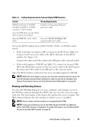
...iKVM (see "Enabling iKVM Access to the SIP. Table 2-2. See Figure 1-16. Connect the other end of blades. The Slot column indicates the slot number in OSCAR. Initial System Configuration 41 You can view the servers by... to the CMC though the iKVM, an additional option, Dell CMC Console, is the chassis slot number the server occupies. Cabling Requirements for External Digital KVM Switches Switch Tiering Requirements Dell PowerConnect 2161DS, 4161DS, 2161DS-2, 2321DS (version 1.3.40.0... in order to view, configure, and manage servers in the M1000e enclosure through the iKVM.
...iKVM (see "Enabling iKVM Access to the SIP. Table 2-2. See Figure 1-16. Connect the other end of blades. The Slot column indicates the slot number in OSCAR. Initial System Configuration 41 You can view the servers by... to the CMC though the iKVM, an additional option, Dell CMC Console, is the chassis slot number the server occupies. Cabling Requirements for External Digital KVM Switches Switch Tiering Requirements Dell PowerConnect 2161DS, 4161DS, 2161DS-2, 2321DS (version 1.3.40.0... in order to view, configure, and manage servers in the M1000e enclosure through the iKVM.
Hardware Owner's Manual
Page 14
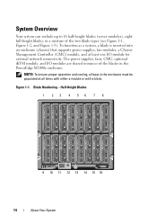
..., fans, CMC, optional iKVM module, and I /O module for external network connectivity. Figure 1-1. Blade Numbering - To function as a system, a blade is inserted into an enclosure (chassis) that supports power supplies, fan modules, a Chassis Management Controller (CMC) module, and at all bays in the PowerEdge M1000e enclosure. NOTE: To ensure proper operation and cooling, all times with either...
..., fans, CMC, optional iKVM module, and I /O module for external network connectivity. Figure 1-1. Blade Numbering - To function as a system, a blade is inserted into an enclosure (chassis) that supports power supplies, fan modules, a Chassis Management Controller (CMC) module, and at all bays in the PowerEdge M1000e enclosure. NOTE: To ensure proper operation and cooling, all times with either...

Hardware Owner's Manual
Page 194
... Memory Modules WARNING: The memory modules are hot to the touch for M905. See "Removing a Blade" on page 149. 3 Locate the memory module sockets. If a memory module blank is installed in the blade chassis to cool before handling them. Installing and Removing a Memory Module or Memory Module Blank 2 1 1 memory module 3 ejectors (2) 5 alignment key... 1 through step 8 in "Removing the System Board" on page 255. 5 Press the ejectors on the memory module socket down . See Figure 7-12 or Figure 7-11. 4 PowerEdge M910 and M905 systems only -
... Memory Modules WARNING: The memory modules are hot to the touch for M905. See "Removing a Blade" on page 149. 3 Locate the memory module sockets. If a memory module blank is installed in the blade chassis to cool before handling them. Installing and Removing a Memory Module or Memory Module Blank 2 1 1 memory module 3 ejectors (2) 5 alignment key... 1 through step 8 in "Removing the System Board" on page 255. 5 Press the ejectors on the memory module socket down . See Figure 7-12 or Figure 7-11. 4 PowerEdge M910 and M905 systems only -

Hardware Owner's Manual
Page 196
... module pops out of the latch. 4 PowerEdge M910 and M905 systems only - NOTE: Hold the mezzanine interface card by pressing the ridged area on the latch with your thumb, and lifting the end of the socket. See step 1 through step 9 in the blade chassis to access the memory modules, reinstall the ...system board. 7 Close the blade. You must slide the system board back in "Removing the System Board" on page 255. 5 Press down and ...
... module pops out of the latch. 4 PowerEdge M910 and M905 systems only - NOTE: Hold the mezzanine interface card by pressing the ridged area on the latch with your thumb, and lifting the end of the socket. See step 1 through step 9 in the blade chassis to access the memory modules, reinstall the ...system board. 7 Close the blade. You must slide the system board back in "Removing the System Board" on page 255. 5 Press down and ...

Hardware Owner's Manual
Page 198
...of the interface card align with a matching I/O module(s). I /O Modules" on page 145. 2 Open the blade. If installed, the mezzanine card(s) must be used in such a way that the connectors on the bottom of the blade chassis. 8 Close the card retention latch to the interface-card connectors. 11 Close the... blade. See "Closing the Blade" on the latch with your thumb and lifting the end of optional mezzanine cards. See "...
...of the interface card align with a matching I/O module(s). I /O Modules" on page 145. 2 Open the blade. If installed, the mezzanine card(s) must be used in such a way that the connectors on the bottom of the blade chassis. 8 Close the card retention latch to the interface-card connectors. 11 Close the... blade. See "Closing the Blade" on the latch with your thumb and lifting the end of optional mezzanine cards. See "...

Hardware Owner's Manual
Page 203
... Figure 3-23. See "Installing a Blade" on page 159. 7 Install the blade. See "Removing a Blade" on page 159. 9 Install the blade. Installing Blade Components 203 See "Closing the Blade" on page 145. 2 Open the blade. Removing a Mezzanine Card 1 Remove the blade. See "Installing a Blade" on the latch with your thumb, and lifting the end of the blade chassis. 7 Close the retention latch...
... Figure 3-23. See "Installing a Blade" on page 159. 7 Install the blade. See "Removing a Blade" on page 159. 9 Install the blade. Installing Blade Components 203 See "Closing the Blade" on page 145. 2 Open the blade. Removing a Mezzanine Card 1 Remove the blade. See "Installing a Blade" on the latch with your thumb, and lifting the end of the blade chassis. 7 Close the retention latch...
Hardware Owner's Manual
Page 253
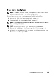
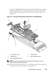
... page 248. 4 Lift the latches at each blade to remove and replace the hard-drive backplane: 1 Remove the blade. See Figure 3-57. Follow these steps to maintain proper airflow, even when the blade is in a diskless configurations. NOTE: If you are removing more than one hard drive, label them so you... can replace them in each end of the backplane, then lift the backplane from the blade chassis. Installing Blade Components 253 NOTE: You must be installed in their original locations. See "Removing a Hard Drive" on page 145. 2 Open the...
... page 248. 4 Lift the latches at each blade to remove and replace the hard-drive backplane: 1 Remove the blade. See Figure 3-57. Follow these steps to maintain proper airflow, even when the blade is in a diskless configurations. NOTE: If you are removing more than one hard drive, label them so you... can replace them in each end of the backplane, then lift the backplane from the blade chassis. Installing Blade Components 253 NOTE: You must be installed in their original locations. See "Removing a Hard Drive" on page 145. 2 Open the...

Hardware Owner's Manual
Page 256
9 To remove a full-height blade system board: a Use the thumb and index fingers of the chassis. Removing and Installing a System Board - Figure 3-58. See Figure 3-58. b Keeping the retention pin raised with your index finger, press the corner of the blade chassis with your thumb to slide the system board out of the open end of your right hand to lift the system board retention pin. Full-Height Blades (PowerEdge M905 Shown) 2 1 4 3 1 system board 3 tabs on system chassis 2 system board retention pin 4 slots in system board tray 256 Installing Blade Components
9 To remove a full-height blade system board: a Use the thumb and index fingers of the chassis. Removing and Installing a System Board - Figure 3-58. See Figure 3-58. b Keeping the retention pin raised with your index finger, press the corner of the blade chassis with your thumb to slide the system board out of the open end of your right hand to lift the system board retention pin. Full-Height Blades (PowerEdge M905 Shown) 2 1 4 3 1 system board 3 tabs on system chassis 2 system board retention pin 4 slots in system board tray 256 Installing Blade Components
Hardware Owner's Manual
Page 257
... their original locations. 10 Ensure that the I/O connector cover is still in place on the I/O connector at the back of the chassis. To remove a half-height blade system board, hold the blade chassis with one hand, lift and pull the system board retention latch with the other hand, and then slide the system board...
... their original locations. 10 Ensure that the I/O connector cover is still in place on the I/O connector at the back of the chassis. To remove a half-height blade system board, hold the blade chassis with one hand, lift and pull the system board retention latch with the other hand, and then slide the system board...
Hardware Owner's Manual
Page 259
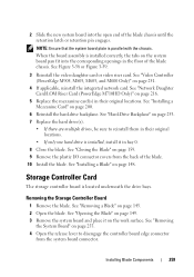
... the board assembly is installed, install it on page 200. 6 Reinstall the hard-drive backplane. See "Closing the Blade" on the system board pan fit into the open end of the blade chassis. See "Video Controller (PowerEdge M905, M805, M605, and M600 Only)" on page 148. See "Removing the System Board" on page 145...
... the board assembly is installed, install it on page 200. 6 Reinstall the hard-drive backplane. See "Closing the Blade" on the system board pan fit into the open end of the blade chassis. See "Video Controller (PowerEdge M905, M805, M605, and M600 Only)" on page 148. See "Removing the System Board" on page 145...
Hardware Owner's Manual
Page 263
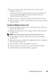
... 263 NOTE: Ensure that secure the midplane interface card to the chassis. See "Installing a Blade" on page 200. 5 Close the blade. Installing the Midplane Interface Card 1 Position the midplane interface card into the blade chassis by sliding it out of the chassis. To disconnect the power and data cables, press the release latch on the connector...
... 263 NOTE: Ensure that secure the midplane interface card to the chassis. See "Installing a Blade" on page 200. 5 Close the blade. Installing the Midplane Interface Card 1 Position the midplane interface card into the blade chassis by sliding it out of the chassis. To disconnect the power and data cables, press the release latch on the connector...

Fabric OS Command Reference Manual Supporting Fabric
Page 502
...is one of this command is most common are tested. 2 itemList The exact type of list varies, depending on the current blade (specified with --slot number) are tested. however, the most commonly used by either the area portion of the ports Fibre ...ports Chips, ASICs within the current switch (selected during Telnet login) are blade ports and user ports. TABLE 22 Object descriptions Type Grouping Description BPORTS UPORTS QUADS CHIPS MINIS SLOTS INDEX Blade Switch Blade Blade Blade Chassis N/A Blade ports, internal and external ports User ports, ports with slot/port notation....
...is one of this command is most common are tested. 2 itemList The exact type of list varies, depending on the current blade (specified with --slot number) are tested. however, the most commonly used by either the area portion of the ports Fibre ...ports Chips, ASICs within the current switch (selected during Telnet login) are blade ports and user ports. TABLE 22 Object descriptions Type Grouping Description BPORTS UPORTS QUADS CHIPS MINIS SLOTS INDEX Blade Switch Blade Blade Blade Chassis N/A Blade ports, internal and external ports User ports, ports with slot/port notation....


