

Glossary
Page 8
SVGA - system configuration information - System Setup program - A port on the devices or by setting features such as the last device at each disk used. Uninterruptible power supply. See memory key. 8 SMP -...IP - Transmission Control Protocol/Internet Protocol. When such devices are video standards for operation. U-DIMM - Universal Serial Bus. Symmetric multiprocessing. system memory - Because the System Setup program is running. SNMP - striping - The amount of disks in an array, but only uses a portion of the space on each processor has equal access...
SVGA - system configuration information - System Setup program - A port on the devices or by setting features such as the last device at each disk used. Uninterruptible power supply. See memory key. 8 SMP -...IP - Transmission Control Protocol/Internet Protocol. When such devices are video standards for operation. U-DIMM - Universal Serial Bus. Symmetric multiprocessing. system memory - Because the System Setup program is running. SNMP - striping - The amount of disks in an array, but only uses a portion of the space on each processor has equal access...
Information Update - Intel Xeon 5600 Series Processors
Page 2
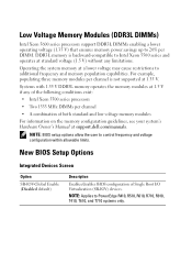
... control frequency and voltage configuration within allowable limits. Operating the system memory at support.dell.com/manuals. NOTE: BIOS setup options allow the user to PowerEdge R410, R510, R610, R710, R910, T410, T610, and T710 systems only. New BIOS Setup Options Integrated Devices Screen Option SR-IOV-Global Enable (Disabled default) Description Enables/disables...
... control frequency and voltage configuration within allowable limits. Operating the system memory at support.dell.com/manuals. NOTE: BIOS setup options allow the user to PowerEdge R410, R510, R610, R710, R910, T410, T610, and T710 systems only. New BIOS Setup Options Integrated Devices Screen Option SR-IOV-Global Enable (Disabled default) Description Enables/disables...
Information Update - Intel Xeon 5600 Series Processors
Page 4
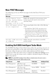
... system to set the processor performance in the Processor Settings screen of the system setup, the feature can be enabled or disabled using the following BIOS setup options: NOTE: The Dell BIOS Intelligent Turbo Mode is disabled when the turbo mode is not supported This ...message displays when either of system memory, system X.X GB, System Memory memory speed, and current system memory Speed: XXX MHz, operating voltage. Non-ECC DIMM detected Displays when the system detects a non-ECC on PowerEdge...
... system to set the processor performance in the Processor Settings screen of the system setup, the feature can be enabled or disabled using the following BIOS setup options: NOTE: The Dell BIOS Intelligent Turbo Mode is disabled when the turbo mode is not supported This ...message displays when either of system memory, system X.X GB, System Memory memory speed, and current system memory Speed: XXX MHz, operating voltage. Non-ECC DIMM detected Displays when the system detects a non-ECC on PowerEdge...
Information Update
Page 23
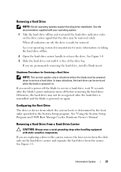
... and UEFI Boot Manager" in the System Setup program. Shutdown Procedure for Servicing a Hard Drive NOTE: This section applies only to situations where the blade must be removed safely. If you need to ...
... and UEFI Boot Manager" in the System Setup program. Shutdown Procedure for Servicing a Hard Drive NOTE: This section applies only to situations where the blade must be removed safely. If you need to ...
Information Update - M605, M600
Page 1
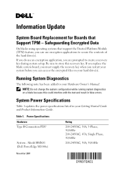
... key during system setup. If you are prompted to secure the contents of the hard drive(s). Be sure to your Getting Started Guide and Product Information Guide. If you replace the blade system board, you must supply the recovery key when you restart your hard drive(s). Model BMX01 (Dell PowerEdge M1000e) Rating 200-240VAC...
... key during system setup. If you are prompted to secure the contents of the hard drive(s). Be sure to your Getting Started Guide and Product Information Guide. If you replace the blade system board, you must supply the recovery key when you restart your hard drive(s). Model BMX01 (Dell PowerEdge M1000e) Rating 200-240VAC...
Information Update - Processor Installation
Page 9
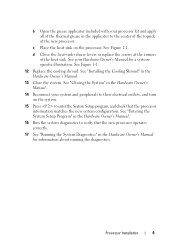
... "Installing the Cooling Shroud" in the Hardware Owner's Manual. 13 Close the system. See "Entering the System Setup Program" in the Hardware Owner's Manual. 16 Run the system diagnostics to enter the System Setup program, and check that the new processor operates correctly. 17 See "Running the System Diagnostics" in the Hardware...
... "Installing the Cooling Shroud" in the Hardware Owner's Manual. 13 Close the system. See "Entering the System Setup Program" in the Hardware Owner's Manual. 16 Run the system diagnostics to enter the System Setup program, and check that the new processor operates correctly. 17 See "Running the System Diagnostics" in the Hardware...

Getting Started Guide
Page 9
... Microsoft Windows Web Server 2008 (x86) Edition with SP2 Microsoft Windows Server 2008 Standard and Enterprise (x86) Editions with the system. Complete the Operating System Setup If you purchased a preinstalled operating system, see the installation and configuration documentation for your system. To install an operating system for the first time, see...
... Microsoft Windows Web Server 2008 (x86) Edition with SP2 Microsoft Windows Server 2008 Standard and Enterprise (x86) Editions with the system. Complete the Operating System Setup If you purchased a preinstalled operating system, see the installation and configuration documentation for your system. To install an operating system for the first time, see...
Dell PowerEdge M1000e Configuration Guide
Page 3
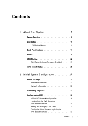
Contents 1 About Your System 7 System Overview 7 LCD Module 11 LCD Module Menus 12 Back-Panel Features 14 Blades 15 CMC Module 22 CMC Daisy Chaining (Enclosure Stacking) . . . . 23 iKVM Switch Module 25 2 Initial System Configuration 27 Before You Begin 27 Power Requirements 27 Network Information 27 Initial Setup Sequence 27 Configuring the CMC 28 Initial CMC Network Configuration 28 Logging in to the CMC Using the Web-Based Interface 31 Adding and Managing CMC Users 32 Configuring iDRAC Networking Using the Web-Based Interface 33 Contents 3
Contents 1 About Your System 7 System Overview 7 LCD Module 11 LCD Module Menus 12 Back-Panel Features 14 Blades 15 CMC Module 22 CMC Daisy Chaining (Enclosure Stacking) . . . . 23 iKVM Switch Module 25 2 Initial System Configuration 27 Before You Begin 27 Power Requirements 27 Network Information 27 Initial Setup Sequence 27 Configuring the CMC 28 Initial CMC Network Configuration 28 Logging in to the CMC Using the Web-Based Interface 31 Adding and Managing CMC Users 32 Configuring iDRAC Networking Using the Web-Based Interface 33 Contents 3

Dell PowerEdge M1000e Configuration Guide
Page 12
... in the enclosure using this menu. LCD Module Menus Table 1-1. An active blade is indicated by a green rectangle. LCD Setup Menu You can highlight each blade in a menu and to the LCD Setup Menu, Server Menu, and Enclosure Menu. Use this condition is indicated by an amber rectangle. • To select a blade...
... in the enclosure using this menu. LCD Module Menus Table 1-1. An active blade is indicated by a green rectangle. LCD Setup Menu You can highlight each blade in a menu and to the LCD Setup Menu, Server Menu, and Enclosure Menu. Use this condition is indicated by an amber rectangle. • To select a blade...
Dell PowerEdge M1000e Configuration Guide
Page 27
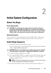
Network Information If your network uses static addressing, you have configured the switch modules, as the system does not operate at support.dell.com/manuals. See Figure 1-4. You can select only one AC power input, as described in "Configuring the I/O Modules" on the...to the enclosure control panel (see Figure 1-4) or to an electrical outlet. Initial System Configuration 27 For more information, see Figure 1-16). Initial Setup Sequence 1 Unpack the enclosure and install it in the enclosure. NOTE: Connecting a keyboard, video, and mouse to the enclosure front panel disables...
Network Information If your network uses static addressing, you have configured the switch modules, as the system does not operate at support.dell.com/manuals. See Figure 1-4. You can select only one AC power input, as described in "Configuring the I/O Modules" on the...to the enclosure control panel (see Figure 1-4) or to an electrical outlet. Initial System Configuration 27 For more information, see Figure 1-16). Initial Setup Sequence 1 Unpack the enclosure and install it in the enclosure. NOTE: Connecting a keyboard, video, and mouse to the enclosure front panel disables...

Dell PowerEdge M1000e Configuration Guide
Page 32
... added security, it is calvin. NOTE: This field is available through the Help link at the top right corner of the root account during initial setup. NOTE: The default CMC user name is root, and the password is highly recommended that you can log in as either a CMC user or as...
... added security, it is calvin. NOTE: This field is available through the Help link at the top right corner of the root account during initial setup. NOTE: The default CMC user name is root, and the password is highly recommended that you can log in as either a CMC user or as...

Dell PowerEdge M1000e Configuration Guide
Page 34
2 Click the plus (+) symbol next to Chassis in the system tree and then click Setup Deploy First Boot Device. You can set the default boot device and you can also set the first boot device for some or all ...servers in the chassis: 1 Log in to the CMC Web-based interface. 2 Click Servers in the left column, then click Servers. 3 Click Setup Deploy. 4 Select the protocol for the iDRAC setting (IPv4 and/or IPv6). 5 Enable the LAN for the iDRAC on the next boot cycle, select...
2 Click the plus (+) symbol next to Chassis in the system tree and then click Setup Deploy First Boot Device. You can set the default boot device and you can also set the first boot device for some or all ...servers in the chassis: 1 Log in to the CMC Web-based interface. 2 Click Servers in the left column, then click Servers. 3 Click Setup Deploy. 4 Select the protocol for the iDRAC setting (IPv4 and/or IPv6). 5 Enable the LAN for the iDRAC on the next boot cycle, select...

Dell PowerEdge M1000e Configuration Guide
Page 38
... from iKVM. 5 Click Apply to save the setting. NOTE: The default iKVM firmware image name is displayed. 3 Click the Setup tab. Configuring the Optional iKVM Switch Module Enabling iKVM Access to the Dell CMC Console Enabling access to the CMC allows you to confirm the action. 7 Click Yes to continue. The iKVM...
... from iKVM. 5 Click Apply to save the setting. NOTE: The default iKVM firmware image name is displayed. 3 Click the Setup tab. Configuring the Optional iKVM Switch Module Enabling iKVM Access to the Dell CMC Console Enabling access to the CMC allows you to confirm the action. 7 Click Yes to continue. The iKVM...

Dell PowerEdge M1000e Configuration Guide
Page 39
...Requirements for a Server Interface Pod (SIP) (see Table 2-1). To configure the analog switch: 1 Press to open the OSCAR Main dialog box. 2 Click Setup Devices Device Modify. 3 Select the 16-port option to match the number of blades in slot order, and set and you to soft... switch to a server without the need for External Analog KVM Switches Switch Dell PowerConnect 180AS, 2160AS (version 1.0.3.2 or later) Avocent Autoview 2020, 2030 (version 1.6.0.4 or later) Avocent Autoview 1400, 1500, 2000, 1415, 1515, ...
...Requirements for a Server Interface Pod (SIP) (see Table 2-1). To configure the analog switch: 1 Press to open the OSCAR Main dialog box. 2 Click Setup Devices Device Modify. 3 Select the 16-port option to match the number of blades in slot order, and set and you to soft... switch to a server without the need for External Analog KVM Switches Switch Dell PowerConnect 180AS, 2160AS (version 1.0.3.2 or later) Avocent Autoview 2020, 2030 (version 1.6.0.4 or later) Avocent Autoview 1400, 1500, 2000, 1415, 1515, ...

Dell PowerEdge M1000e Configuration Guide
Page 53
... external uplinks. The expansion slot on the front panel can be installed in Fabric A, B, or C. Select DHCP Mode Enabled if your network. - 3 Select the Setup tab. Dell PowerConnect-KR 8024-k Switch The PowerConnect M8024-k switch provides 16 internal 10 GbE ports, four external 10 GbE SFP+ ports, and one 10 GbE expansion...
... external uplinks. The expansion slot on the front panel can be installed in Fabric A, B, or C. Select DHCP Mode Enabled if your network. - 3 Select the Setup tab. Dell PowerConnect-KR 8024-k Switch The PowerConnect M8024-k switch provides 16 internal 10 GbE ports, four external 10 GbE SFP+ ports, and one 10 GbE expansion...
Hardware Owner's Manual
Page 5
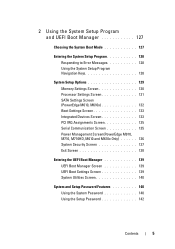
... Manager 127 Choosing the System Boot Mode 127 Entering the System Setup Program 128 Responding to Error Messages 128 Using the System Setup Program Navigation Keys 128 System Setup Options 129 Memory Settings Screen 130 Processor Settings Screen 131 SATA Settings Screen (PowerEdge M610, M610x 132 Boot Settings Screen 133 Integrated Devices Screen 133...
... Manager 127 Choosing the System Boot Mode 127 Entering the System Setup Program 128 Responding to Error Messages 128 Using the System Setup Program Navigation Keys 128 System Setup Options 129 Memory Settings Screen 130 Processor Settings Screen 131 SATA Settings Screen (PowerEdge M610, M610x 132 Boot Settings Screen 133 Integrated Devices Screen 133...

Hardware Owner's Manual
Page 13
... information, see the documentation for PXE boot. 1 About Your System Accessing System Features During Start-up Keystroke Description Enters the System Setup program. Boot Mode set to UEFI: Enters the UEFI Boot Manager, which enables you to manage your system from which allows access...log (SEL) and configuration of remote access to configure NIC settings for your integrated NIC. Enters PXE boot (if enabled in System Setup program). Enters the SAS Configuration Utility. NOTE: LifeCycle Controller is supported on page 127. See your SAS adapter documentation for your RAID ...
... information, see the documentation for PXE boot. 1 About Your System Accessing System Features During Start-up Keystroke Description Enters the System Setup program. Boot Mode set to UEFI: Enters the UEFI Boot Manager, which enables you to manage your system from which allows access...log (SEL) and configuration of remote access to configure NIC settings for your integrated NIC. Enters PXE boot (if enabled in System Setup program). Enters the SAS Configuration Utility. NOTE: LifeCycle Controller is supported on page 127. See your SAS adapter documentation for your RAID ...

Hardware Owner's Manual
Page 19
... Screen Navigation Keys Keys Left and right arrows Up arrow or down arrow Center button Action Move between screens. LCD module features include: • A deployment setup wizard that allows you to configure the CMC module's network settings during initial system set up. • Menus to the next screen. Select and save...
... Screen Navigation Keys Keys Left and right arrows Up arrow or down arrow Center button Action Move between screens. LCD module features include: • A deployment setup wizard that allows you to configure the CMC module's network settings during initial system set up. • Menus to the next screen. Select and save...

Hardware Owner's Manual
Page 21
... in each blade in the enclosure. Main Menu The Main Menu options include links to the LCD Setup Menu, Server Menu, and Enclosure Menu. An active blade is designated by a gray rectangle. LCD Setup Menu You can change the default language and start-up screen for the LCD menu screens using the...
... in each blade in the enclosure. Main Menu The Main Menu options include links to the LCD Setup Menu, Server Menu, and Enclosure Menu. An active blade is designated by a gray rectangle. LCD Setup Menu You can change the default language and start-up screen for the LCD menu screens using the...

Hardware Owner's Manual
Page 29
...8226; Press and hold the button to turn off the blade immediately. The blade power button is enabled by default by the System Setup program.(If the power button option is being remotely identified via the CMC. For detailed information on installing a blade, see "Installing ... Blade" on the blade. The blade is disabled, you turn off the blade using the power button and the blade is in the M1000e enclosure. Normal operating state. Blade Control Panel Features Feature Icon Blade power indicator Blade status/ identification indicator Blade power N/A button USB connector...
...8226; Press and hold the button to turn off the blade immediately. The blade power button is enabled by default by the System Setup program.(If the power button option is being remotely identified via the CMC. For detailed information on installing a blade, see "Installing ... Blade" on the blade. The blade is disabled, you turn off the blade using the power button and the blade is in the M1000e enclosure. Normal operating state. Blade Control Panel Features Feature Icon Blade power indicator Blade status/ identification indicator Blade power N/A button USB connector...


