

Rack Installation Guide
Page 7
...for rack stability and safety. Warranty information might be installed in this task. SAFETY: Rack Mounting of two people should accomplish this document or as a separate document. Rack Installation Guide 5 The installation of system and rack complies with all liability and warranties... in connection with your system and working environment from potential damage. Systems are intended to be sure that the rack meets the specifications of a Dell rack. It ...
...for rack stability and safety. Warranty information might be installed in this task. SAFETY: Rack Mounting of two people should accomplish this document or as a separate document. Rack Installation Guide 5 The installation of system and rack complies with all liability and warranties... in connection with your system and working environment from potential damage. Systems are intended to be sure that the rack meets the specifications of a Dell rack. It ...
Rack Installation Guide
Page 8
... have square or round holes. One rack kit is required for each system to the floor, and that the full weight of a rack; General Installation Instructions This installation guide provides instructions for joined multiple racks before extending a component from the rack. • Use caution when pressing the component rail release latches and sliding... that the rack is level and stable before working on the rack, make sure that the stabilizers are secured to the rack, extended to be installed in the rack cabinet. 6 Rack Installation Guide
... have square or round holes. One rack kit is required for each system to the floor, and that the full weight of a rack; General Installation Instructions This installation guide provides instructions for joined multiple racks before extending a component from the rack. • Use caution when pressing the component rail release latches and sliding... that the rack is level and stable before working on the rack, make sure that the stabilizers are secured to the rack, extended to be installed in the rack cabinet. 6 Rack Installation Guide
Rack Installation Guide
Page 9
... important when systems are important to prevent injury to yourself and to install the next system. Use only the rack kit for another system may occur. Rack Installation Guide 7 CAUTION: When installing multiple systems in the following subsections when installing your Product Information Guide for another system. Retract the leveling feet when relocating the rack cabinet...
... important when systems are important to prevent injury to yourself and to install the next system. Use only the rack kit for another system may occur. Rack Installation Guide 7 CAUTION: When installing multiple systems in the following subsections when installing your Product Information Guide for another system. Retract the leveling feet when relocating the rack cabinet...
Rack Installation Guide
Page 10
... rack doors 2 Marking the rack (if necessary) 3 Installing the rail assemblies in the rack: • RapidRails installation • VersaRails installation 4 Installing the system in the rack 5 Routing and managing data cables • Installing the strain-relief bar • Using the I/O cable ..., for instructions on racks joined to be used • A measuring ruler or tape measure 8 Rack Installation Guide Failure to install stabilizers accordingly before installing components in marking the mounting holes to other racks. The stabilizer feet help prevent the rack from tipping ...
... rack doors 2 Marking the rack (if necessary) 3 Installing the rail assemblies in the rack: • RapidRails installation • VersaRails installation 4 Installing the system in the rack 5 Routing and managing data cables • Installing the strain-relief bar • Using the I/O cable ..., for instructions on racks joined to be used • A measuring ruler or tape measure 8 Rack Installation Guide Failure to install stabilizers accordingly before installing components in marking the mounting holes to other racks. The stabilizer feet help prevent the rack from tipping ...
Rack Installation Guide
Page 11
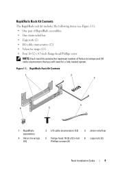
... contains the maximum number of Velcro tie wraps and I /O cable enumerators (12) 3 strain-relief bar 5 flange-head 10-32 x 0.5-inch 6 cage nuts (2) Phillips screws (4) Rack Installation Guide 9
... contains the maximum number of Velcro tie wraps and I /O cable enumerators (12) 3 strain-relief bar 5 flange-head 10-32 x 0.5-inch 6 cage nuts (2) Phillips screws (4) Rack Installation Guide 9

Rack Installation Guide
Page 12
... tie wraps and I /O cable enumerators (12) 3 strain-relief bar 4 Velcro tie wraps 5 flange-head 10-32 x 0.5-inch 6 clip nuts (2) (15) Phillips screws (12) 10 Rack Installation Guide
... tie wraps and I /O cable enumerators (12) 3 strain-relief bar 4 Velcro tie wraps 5 flange-head 10-32 x 0.5-inch 6 clip nuts (2) (15) Phillips screws (12) 10 Rack Installation Guide
Rack Installation Guide
Page 13
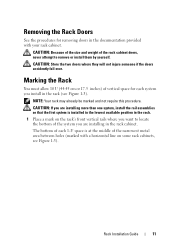
... the Rack Doors See the procedures for each 1-U space is at the middle of the system you are installing more than one system, install the rail assemblies so that the first system is installed in the lowest available position in the rack. 1 Place a mark on the rack's front vertical rails where...Store the two doors where they will not injure someone if the doors accidently fall over. The bottom of each system you are installing in the rack cabinet. Rack Installation Guide 11 Marking the Rack You must allow 10 U (44.45 cm or 17.5 inches) of the rack cabinet doors, never attempt...
... the Rack Doors See the procedures for each 1-U space is at the middle of the system you are installing more than one system, install the rail assemblies so that the first system is installed in the lowest available position in the rack. 1 Place a mark on the rack's front vertical rails where...Store the two doors where they will not injure someone if the doors accidently fall over. The bottom of each system you are installing in the rack cabinet. Rack Installation Guide 11 Marking the Rack You must allow 10 U (44.45 cm or 17.5 inches) of the rack cabinet doors, never attempt...

Rack Installation Guide
Page 14
One Rack Unit 1 U (44 mm or 1.75 inches) 12.7 mm (0.5 inch) 15.9 mm (0.625 inch) 15.9 mm (0.625 inch) 12.7 mm (0.5 inch) 2 Mark the rack's front vertical rails with a felt-tipped pen or masking tape approximately 44.45 cm (17.5 inches) above the original mark you made (or count up 30 holes in a rack that meets CEA-310-E standards). (If you counted holes, place a mark just above the top hole.) This mark or piece of tape indicates where the system's upper edge will be located on the vertical rails (see Figure 1-4). 12 Rack Installation Guide Figure 1-3.
One Rack Unit 1 U (44 mm or 1.75 inches) 12.7 mm (0.5 inch) 15.9 mm (0.625 inch) 15.9 mm (0.625 inch) 12.7 mm (0.5 inch) 2 Mark the rack's front vertical rails with a felt-tipped pen or masking tape approximately 44.45 cm (17.5 inches) above the original mark you made (or count up 30 holes in a rack that meets CEA-310-E standards). (If you counted holes, place a mark just above the top hole.) This mark or piece of tape indicates where the system's upper edge will be located on the vertical rails (see Figure 1-4). 12 Rack Installation Guide Figure 1-3.
Rack Installation Guide
Page 15
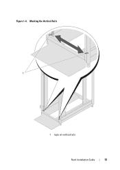
Marking the Vertical Rails 1 1 tape on vertical rails Rack Installation Guide 13 Figure 1-4.
Marking the Vertical Rails 1 1 tape on vertical rails Rack Installation Guide 13 Figure 1-4.
Rack Installation Guide
Page 16
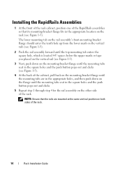
... square holes and the push button pops out and clicks. 5 Repeat step 1 through step 4 for the rail assembly on the other side of the rack. Installing the RapidRails Assemblies 1 At the front of the rack cabinet, position one of the RapidRails assemblies so that the rails are in the appropriate holes... down on the mounting-bracket flange until the mounting tabs are mounted at the same vertical position on both sides of the rack. 14 Rack Installation Guide
... square holes and the push button pops out and clicks. 5 Repeat step 1 through step 4 for the rail assembly on the other side of the rack. Installing the RapidRails Assemblies 1 At the front of the rack cabinet, position one of the RapidRails assemblies so that the rails are in the appropriate holes... down on the mounting-bracket flange until the mounting tabs are mounted at the same vertical position on both sides of the rack. 14 Rack Installation Guide

Rack Installation Guide
Page 17
Installing the RapidRails Assemblies 1 2 3 4 5 front of rack 1 upper mounting tab 4 rail-assembly mountingbracket flange 2 push button 3 lower mounting tab 5 rail assemblies (2) Rack Installation Guide 15 Figure 1-5.
Installing the RapidRails Assemblies 1 2 3 4 5 front of rack 1 upper mounting tab 4 rail-assembly mountingbracket flange 2 push button 3 lower mounting tab 5 rail assemblies (2) Rack Installation Guide 15 Figure 1-5.
Rack Installation Guide
Page 18
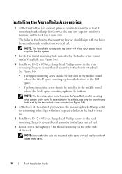
...; The upper mounting screw should be installed in the middle round hole of the 1st-U space counting up from the bottom. NOTE: The two midsection round holes on the VersaRails are mounted at the same vertical position on both sides of the rack. 16 Rack Installation Guide The holes on the front of... the mounting bracket should be installed in the middle round hole of the 6th-U space counting up from the bottom of the 10-U space. •...
...; The upper mounting screw should be installed in the middle round hole of the 1st-U space counting up from the bottom. NOTE: The two midsection round holes on the VersaRails are mounted at the same vertical position on both sides of the rack. 16 Rack Installation Guide The holes on the front of... the mounting bracket should be installed in the middle round hole of the 6th-U space counting up from the bottom of the 10-U space. •...

Rack Installation Guide
Page 19
Figure 1-6. Installing the VersaRails Rail Assemblies 1 2 3 4 5 front of rack 1 rail-assembly mounting- 2 tooled arrow cutouts (2) 3 vertical rails bracket flange 4 Phillips screws (2) 5 rail assemblies (2) Rack Installation Guide 17
Figure 1-6. Installing the VersaRails Rail Assemblies 1 2 3 4 5 front of rack 1 rail-assembly mounting- 2 tooled arrow cutouts (2) 3 vertical rails bracket flange 4 Phillips screws (2) 5 rail assemblies (2) Rack Installation Guide 17
Rack Installation Guide
Page 20
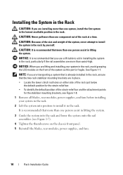
...; Locate the lower clinch nut holes on the chassis front panel. 5 Reinstall the blades, rear modules, power supplies, and fans. 18 Rack Installation Guide It is fragile. NOTE: If you are transporting a system that is recommended that the two rack stabilizer mounting brackets are more than waist-high....CAUTION: Because of the size and weight of the system, never attempt to install it in lifting the system. 3 Guide the system into position to install the system in the rack. CAUTION: It is already installed in the rack, ensure that more than one component out of the strain-...
...; Locate the lower clinch nut holes on the chassis front panel. 5 Reinstall the blades, rear modules, power supplies, and fans. 18 Rack Installation Guide It is fragile. NOTE: If you are transporting a system that is recommended that the two rack stabilizer mounting brackets are more than waist-high....CAUTION: Because of the size and weight of the system, never attempt to install it in lifting the system. 3 Guide the system into position to install the system in the rack. CAUTION: It is already installed in the rack, ensure that more than one component out of the strain-...

Rack Installation Guide
Page 21
Figure 1-7. Installing the System in the Rack 1 2 3 1 thumbscrews (4) 2 LCD module 3 rail assemblies (2) Rack Installation Guide 19
Figure 1-7. Installing the System in the Rack 1 2 3 1 thumbscrews (4) 2 LCD module 3 rail assemblies (2) Rack Installation Guide 19
Rack Installation Guide
Page 22
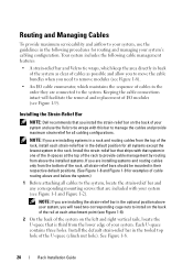
... default strain-relief bar in the default position for all cabling configurations. Each U-space contains three holes. Installing the Strain-Relief Bar NOTE: Dell recommends that you are included with your system and use the guidelines in the following cable management features: ...in the tooled top hole of your system (see Figure 1-1 and Figure 1-2). See Figure 1-8. 20 Rack Installation Guide Install the strain-relief bar that ships with that are installing systems in a rack and routing cables from above your system's cabling configuration. Routing and Managing Cables To...
... default strain-relief bar in the default position for all cabling configurations. Each U-space contains three holes. Installing the Strain-Relief Bar NOTE: Dell recommends that you are included with your system and use the guidelines in the following cable management features: ...in the tooled top hole of your system (see Figure 1-1 and Figure 1-2). See Figure 1-8. 20 Rack Installation Guide Install the strain-relief bar that ships with that are installing systems in a rack and routing cables from above your system's cabling configuration. Routing and Managing Cables To...
Rack Installation Guide
Page 23
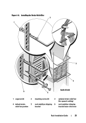
Installing the Strain-Relief Bar 2 1 3 4 back of rack 6 5 1 cage nut (2) 2 4 default strain- 5 relief bar position mounting screw (2) 3 rack stabilizer shipping 6 bracket optional strain-relief bar (for upward cabling) rack stabilizer shipping bracket lower clinch nut Rack Installation Guide 21 Figure 1-8.
Installing the Strain-Relief Bar 2 1 3 4 back of rack 6 5 1 cage nut (2) 2 4 default strain- 5 relief bar position mounting screw (2) 3 rack stabilizer shipping 6 bracket optional strain-relief bar (for upward cabling) rack stabilizer shipping bracket lower clinch nut Rack Installation Guide 21 Figure 1-8.
Rack Installation Guide
Page 24
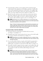
... the topmost I/O cables, arranging them as they cascade over the strain-relief bar, allowing maximum airflow and serviceability for your system (see Figure 1-9). 22 Rack Installation Guide
... the topmost I/O cables, arranging them as they cascade over the strain-relief bar, allowing maximum airflow and serviceability for your system (see Figure 1-9). 22 Rack Installation Guide
Rack Installation Guide
Page 25
... then wrapping around the cable bundle again, crossing the tie wrap in one with the upper eight cables from both columns. Rack Installation Guide 23 NOTE: Depending on your system configuration, there are included with your cabling configuration, you can group and order the cables in...Each enumerator has the capacity to the strain-relief bar with the lower eight cables from either side of I/O modules during removal and installation. Figure 1-9 shows 16 cables grouped and ordered with two enumerators: one of three graduated thicknesses of the enumerator. NOTE: Ensure that...
... then wrapping around the cable bundle again, crossing the tie wrap in one with the upper eight cables from both columns. Rack Installation Guide 23 NOTE: Depending on your system configuration, there are included with your cabling configuration, you can group and order the cables in...Each enumerator has the capacity to the strain-relief bar with the lower eight cables from either side of I/O modules during removal and installation. Figure 1-9 shows 16 cables grouped and ordered with two enumerators: one of three graduated thicknesses of the enumerator. NOTE: Ensure that...
Rack Installation Guide
Page 26
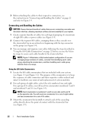
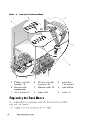
This completes the rack installation of your rack cabinets. Securing the Cables to the Rack 2 3 4 5 1 6 7 9 8 1 I/O cable enumerator (segments 1-8) 4 fiber optic cable connectors (16) 7 Velcro tie wraps (15) 2 I/O cable enumerator (segments 9-16) 5 fiber optic cables (16) 3 cable notches (3 per segment) 6 strain-relief bar 8 power cables 9 vertical rail Replacing the Rack Doors See the procedures for replacing doors in the documentation provided with your system. 24 Rack Installation Guide Figure 1-9.
This completes the rack installation of your rack cabinets. Securing the Cables to the Rack 2 3 4 5 1 6 7 9 8 1 I/O cable enumerator (segments 1-8) 4 fiber optic cable connectors (16) 7 Velcro tie wraps (15) 2 I/O cable enumerator (segments 9-16) 5 fiber optic cables (16) 3 cable notches (3 per segment) 6 strain-relief bar 8 power cables 9 vertical rail Replacing the Rack Doors See the procedures for replacing doors in the documentation provided with your system. 24 Rack Installation Guide Figure 1-9.


