

Glossary
Page 8
...Protocol/Internet Protocol. Some devices (such as password protection. A port on a network hub or switch used . A battery-powered unit that automatically supplies power to enable or disable the termination on these devices by a "stripe" is running. USB devices can be connected and disconnected...disk. SNMP - Because the System Setup program is installed and how the system should be terminated to other hubs or switches without requiring a crossover cable. A USB connector provides a single connection point for multiple USB-compliant devices, such as the processor(s), RAM, ...
...Protocol/Internet Protocol. Some devices (such as password protection. A port on a network hub or switch used . A battery-powered unit that automatically supplies power to enable or disable the termination on these devices by a "stripe" is running. USB devices can be connected and disconnected...disk. SNMP - Because the System Setup program is installed and how the system should be terminated to other hubs or switches without requiring a crossover cable. A USB connector provides a single connection point for multiple USB-compliant devices, such as the processor(s), RAM, ...

Information Update - Power Infrastructure Sizing
Page 1
... power capping features enabled from Dell may result in an infrastructure that regulatory and safety guidance is specific to the system configuration and to understand peak power consumption for the configuration and workload, the 500W power ...power capping at 1000W and the characterization results in a rack, the total load can be used for sizing the infrastructure. Using PDUs with power capping can be used for infrastructure sizing. The power supply-rated approach requires additional power and cooling and results in a significantly different power consumption requirement...
... power capping features enabled from Dell may result in an infrastructure that regulatory and safety guidance is specific to the system configuration and to understand peak power consumption for the configuration and workload, the 500W power ...power capping at 1000W and the characterization results in a rack, the total load can be used for sizing the infrastructure. Using PDUs with power capping can be used for infrastructure sizing. The power supply-rated approach requires additional power and cooling and results in a significantly different power consumption requirement...
Information Update
Page 11
... for complete instructions on how to configure and operate the CMC module. NOTE: See the latest Dell Chassis Management Controller User's Guide at support.dell.com for complete instructions on . The following software components are included with an older CMC firmware version,...by default, will not power on how to configure and operate the CMC module. PowerEdge M610 and M710 blades require CMC firmware version 2.0 or later. Information Update 11 PowerEdge Blades - If you have the option to reset the CMC configuration settings back to an M1000e enclosure with your CMC...
... for complete instructions on how to configure and operate the CMC module. NOTE: See the latest Dell Chassis Management Controller User's Guide at support.dell.com for complete instructions on . The following software components are included with an older CMC firmware version,...by default, will not power on how to configure and operate the CMC module. PowerEdge M610 and M710 blades require CMC firmware version 2.0 or later. Information Update 11 PowerEdge Blades - If you have the option to reset the CMC configuration settings back to an M1000e enclosure with your CMC...
Rack Installation Guide
Page 8
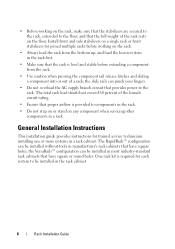
...; configuration can be installed without tools in the rack first. • Make sure that have square or round holes. One rack kit is required for each system to be installed in the rack cabinet. 6 Rack Installation Guide • Before working on the rack. • Always load... installing one or more systems in a rack. The RapidRails™ configuration can be installed in most industry-standard rack cabinets that provides power to components in the rack. • Do not step on or stand on the floor. General Installation Instructions This installation guide provides ...
...; configuration can be installed without tools in the rack first. • Make sure that have square or round holes. One rack kit is required for each system to be installed in the rack cabinet. 6 Rack Installation Guide • Before working on the rack. • Always load... installing one or more systems in a rack. The RapidRails™ configuration can be installed in most industry-standard rack cabinets that provides power to components in the rack. • Do not step on or stand on the floor. General Installation Instructions This installation guide provides ...
Getting Started Guide
Page 7
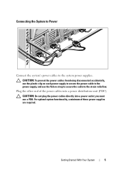
... plastic clip on each power supply to secure the power cable to the power supply, and use a PDU. Connecting the System to Power Connect the system's power cables to the strain-relief bar. you must use the Velcro strap to secure the cable to the system power supplies. Plug the other end of three power supplies are required.
... plastic clip on each power supply to secure the power cable to the power supply, and use a PDU. Connecting the System to Power Connect the system's power cables to the strain-relief bar. you must use the Velcro strap to secure the cable to the system power supplies. Plug the other end of three power supplies are required.
Getting Started Guide
Page 20
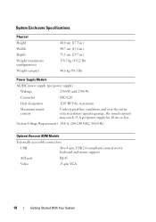
...Requirements 14.4 A, 200-240 VAC, 50/60 Hz Optional Avocent iKVM Module Externally accessible connectors USB Two 4-pin, USB 2.0-compliant connectors for 10 ms or less. maximum Maximum inrush current Under typical line conditions and over the entire system ambient operating range, the inrush current may reach 55 A per power...) 44.0 cm (17.3 in) 44.7 cm (17.6 in) 75.5 cm (29.7 in) 178.3 kg (392.2 lb) 44.6 kg (98.1 lb) Power Supply Module AC/DC power supply (per power supply for keyboard and mouse support ACI port RJ-45 Video 15-pin VGA 18 Getting Started With Your System
...Requirements 14.4 A, 200-240 VAC, 50/60 Hz Optional Avocent iKVM Module Externally accessible connectors USB Two 4-pin, USB 2.0-compliant connectors for 10 ms or less. maximum Maximum inrush current Under typical line conditions and over the entire system ambient operating range, the inrush current may reach 55 A per power...) 44.0 cm (17.3 in) 44.7 cm (17.6 in) 75.5 cm (29.7 in) 178.3 kg (392.2 lb) 44.6 kg (98.1 lb) Power Supply Module AC/DC power supply (per power supply for keyboard and mouse support ACI port RJ-45 Video 15-pin VGA 18 Getting Started With Your System
Dell PowerEdge M1000e Configuration Guide
Page 3
Contents 1 About Your System 7 System Overview 7 LCD Module 11 LCD Module Menus 12 Back-Panel Features 14 Blades 15 CMC Module 22 CMC Daisy Chaining (Enclosure Stacking) . . . . 23 iKVM Switch Module 25 2 Initial System Configuration 27 Before You Begin 27 Power Requirements 27 Network Information 27 Initial Setup Sequence 27 Configuring the CMC 28 Initial CMC Network Configuration 28 Logging in to the CMC Using the Web-Based Interface 31 Adding and Managing CMC Users 32 Configuring iDRAC Networking Using the Web-Based Interface 33 Contents 3
Contents 1 About Your System 7 System Overview 7 LCD Module 11 LCD Module Menus 12 Back-Panel Features 14 Blades 15 CMC Module 22 CMC Daisy Chaining (Enclosure Stacking) . . . . 23 iKVM Switch Module 25 2 Initial System Configuration 27 Before You Begin 27 Power Requirements 27 Network Information 27 Initial Setup Sequence 27 Configuring the CMC 28 Initial CMC Network Configuration 28 Logging in to the CMC Using the Web-Based Interface 31 Adding and Managing CMC Users 32 Configuring iDRAC Networking Using the Web-Based Interface 33 Contents 3
Dell PowerEdge M1000e Configuration Guide
Page 27
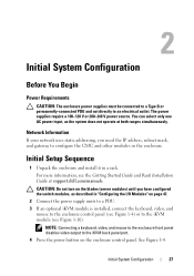
... the switch modules, as the system does not operate at support.dell.com/manuals. CAUTION: Do not turn on the enclosure control panel. Initial System Configuration 27 The power supplies require a 100-120 V or 200-240 V power source. For more information, see Figure 1-16). See Figure 1-4....outlet. Initial Setup Sequence 1 Unpack the enclosure and install it in a rack. 2 Initial System Configuration Before You Begin Power Requirements CAUTION: The enclosure power supplies must be connected to a Type B or permanently-connected PDU and not directly to configure the CMC and other ...
... the switch modules, as the system does not operate at support.dell.com/manuals. CAUTION: Do not turn on the enclosure control panel. Initial System Configuration 27 The power supplies require a 100-120 V or 200-240 V power source. For more information, see Figure 1-16). See Figure 1-4....outlet. Initial Setup Sequence 1 Unpack the enclosure and install it in a rack. 2 Initial System Configuration Before You Begin Power Requirements CAUTION: The enclosure power supplies must be connected to a Type B or permanently-connected PDU and not directly to configure the CMC and other ...

Dell PowerEdge M1000e Configuration Guide
Page 40
... the external analog switch documentation for a SIP (see Table 2-2). 40 Initial System Configuration Connect the other end of the blade to an appropriate power source. 3 Turn on the system. 4 Turn on the external switch. 2 Connect both the analog switch and the system to which the ... taken effect. Many switches may also be displayed as the Dell 2161DS-2 or 4161DS, or a supported Avocent digital KVM switch. If the analog switch requires a USB SIP (see Table 2-1), connect a Cat5 (or newer) cable to slot 1, it may require you to perform additional steps to 01-16. See Figure ...
... the external analog switch documentation for a SIP (see Table 2-2). 40 Initial System Configuration Connect the other end of the blade to an appropriate power source. 3 Turn on the system. 4 Turn on the external switch. 2 Connect both the analog switch and the system to which the ... taken effect. Many switches may also be displayed as the Dell 2161DS-2 or 4161DS, or a supported Avocent digital KVM switch. If the analog switch requires a USB SIP (see Table 2-1), connect a Cat5 (or newer) cable to slot 1, it may require you to perform additional steps to 01-16. See Figure ...
Hardware Owner's Manual
Page 35
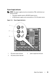
Power Supply Indicators 1 2 3 1 DC power output indicator 3 AC power present indicator 2 power supply fault indicator About Your System 35 Figure 1-16. Power Supply Indicator NOTE: The power supplies must be connected to a PDU, not directly to an electrical outlet. • The power supplies require a 200-240 V power source. • A 2700 W power supply can be connected to a 110 V AC power source.
Power Supply Indicators 1 2 3 1 DC power output indicator 3 AC power present indicator 2 power supply fault indicator About Your System 35 Figure 1-16. Power Supply Indicator NOTE: The power supplies must be connected to a PDU, not directly to an electrical outlet. • The power supplies require a 200-240 V power source. • A 2700 W power supply can be connected to a 110 V AC power source.
Hardware Owner's Manual
Page 41
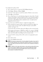
...switch. 2 Connect both the analog switch and the system to an appropriate power source. 3 Turn on the system. 4 Turn on the external switch. For instance, if the iKVM switch is attached to slot 1, it may require you to perform additional steps to display each of the slot locations of...switch OSCAR, instead of the blades in the external analog switch OSCAR. See the external analog switch documentation for additional information. If the analog switch requires a USB SIP (see Table 1-8), connect a Cat5 (or newer) cable to the RJ-45 ACI port on before the system, it would now...
...switch. 2 Connect both the analog switch and the system to an appropriate power source. 3 Turn on the system. 4 Turn on the external switch. For instance, if the iKVM switch is attached to slot 1, it may require you to perform additional steps to display each of the slot locations of...switch OSCAR, instead of the blades in the external analog switch OSCAR. See the external analog switch documentation for additional information. If the analog switch requires a USB SIP (see Table 1-8), connect a Cat5 (or newer) cable to the RJ-45 ACI port on before the system, it would now...
Hardware Owner's Manual
Page 45
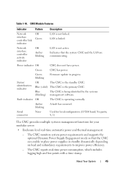
... in progress. Green blinking Firmware update in standby dynamically depending on load and redundancy requirements to improve power efficiency. - Amber blinking A fault has occurred. Fault indicator Off The CMC is linked. Network interface controller activity ...CMC is not linked. The CMC reports real-time power consumption, which includes logging high and low points with a time stamp. Power indicator Off CMC does not have power. The CMC monitors system power requirements and supports the optional Dynamic Power Supply Engagement mode so that the system CMC and...
... in progress. Green blinking Firmware update in standby dynamically depending on load and redundancy requirements to improve power efficiency. - Amber blinking A fault has occurred. Fault indicator Off The CMC is linked. Network interface controller activity ...CMC is not linked. The CMC reports real-time power consumption, which includes logging high and low points with a time stamp. Power indicator Off CMC does not have power. The CMC monitors system power requirements and supports the optional Dynamic Power Supply Engagement mode so that the system CMC and...
Hardware Owner's Manual
Page 85
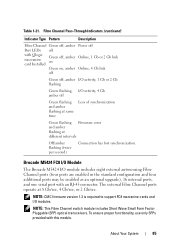
...Small Form Factor Pluggable (SFP) optical transceivers. Fibre Channel Pass-Through Indicators (continued) Indicator Type Pattern Description Fibre Channel Green off, amber Power off Port LEDs off with Qlogic mezzanine card Installed Green off, amber on Online, 1 Gb or 2 Gb link Green on, amber Online... flashing Firmware error and amber flashing at 8 Gb/sec, 4 Gb/sec, or 2 Gb/sec. NOTE: CMC firmware version 1.3 is required to support FC8 mezzanine cards and I /O module includes eight external autosensing Fibre Channel ports (four ports are enabled in the standard configuration and...
...Small Form Factor Pluggable (SFP) optical transceivers. Fibre Channel Pass-Through Indicators (continued) Indicator Type Pattern Description Fibre Channel Green off, amber Power off Port LEDs off with Qlogic mezzanine card Installed Green off, amber on Online, 1 Gb or 2 Gb link Green on, amber Online... flashing Firmware error and amber flashing at 8 Gb/sec, 4 Gb/sec, or 2 Gb/sec. NOTE: CMC firmware version 1.3 is required to support FC8 mezzanine cards and I /O module includes eight external autosensing Fibre Channel ports (four ports are enabled in the standard configuration and...
Hardware Owner's Manual
Page 99
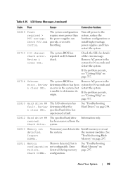
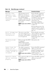
... in the system, but is unable to the system for details of the error message. LCD Status Messages (continued) Code Text Cause Corrective Actions E1629 Power required > PSU wattage. See "Troubleshooting Hard Drives" on page 297. has been removed from the Check drive. E1714 Unknown error. Table 1-25. Remove AC...
... in the system, but is unable to the system for details of the error message. LCD Status Messages (continued) Code Text Cause Corrective Actions E1629 Power required > PSU wattage. See "Troubleshooting Hard Drives" on page 297. has been removed from the Check drive. E1714 Unknown error. Table 1-25. Remove AC...
Hardware Owner's Manual
Page 104
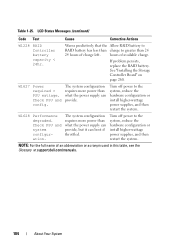
... Controller battery capacity < 24hr. Table 1-25. hours of an abbreviation or acronym used in this table, see the Glossary at support.dell.com/manuals. 104 About Your System The system configuration requires more power than 24 24 hours of charge left. Check PSU and system configuration. Check PSU and config. W1627 Power required > PSU wattage.
... Controller battery capacity < 24hr. Table 1-25. hours of an abbreviation or acronym used in this table, see the Glossary at support.dell.com/manuals. 104 About Your System The system configuration requires more power than 24 24 hours of charge left. Check PSU and system configuration. Check PSU and config. W1627 Power required > PSU wattage.
Hardware Owner's Manual
Page 106
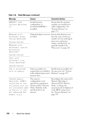
... Ensure that the mezzanine cards installed are supported by the blade. If the NOTE: Applicable to M610x only. (PowerEdge M610x Only)" on page 337. Error: Unsupported mezzanine card configuration. Cables are not installed properly or Mezz IFC ...connected NOTE: Applicable to connections. BIOS does not discover card riser is properly. If required, reseat corrupted. See the console. Ensure that the expansion- Verifying blade power... Cannot Power ON. only. 106 About Your System Blade Messages (continued) Message Causes Corrective Actions Warning...
... Ensure that the mezzanine cards installed are supported by the blade. If the NOTE: Applicable to M610x only. (PowerEdge M610x Only)" on page 337. Error: Unsupported mezzanine card configuration. Cables are not installed properly or Mezz IFC ...connected NOTE: Applicable to connections. BIOS does not discover card riser is properly. If required, reseat corrupted. See the console. Ensure that the expansion- Verifying blade power... Cannot Power ON. only. 106 About Your System Blade Messages (continued) Message Causes Corrective Actions Warning...
Hardware Owner's Manual
Page 110
... detected! See "System Memory" on page 225. have the same cache size, number of cores and logical processors, and power ratings, and that they are Ensure that the memory modules are installed in the indicated processor's Memory" on page 159. ...See "System in a valid configuration. Unused memory detected. See "System Memory" on Invalid memory configuration. memory slots. Reconfigure the memory for required but not installed the processor. A mismatched DIMM is not optimal for mirroring or Advanced ECC Memory Mode. System halted CPU x installed with different ...
... detected! See "System Memory" on page 225. have the same cache size, number of cores and logical processors, and power ratings, and that they are Ensure that the memory modules are installed in the indicated processor's Memory" on page 159. ...See "System in a valid configuration. Unused memory detected. See "System Memory" on Invalid memory configuration. memory slots. Reconfigure the memory for required but not installed the processor. A mismatched DIMM is not optimal for mirroring or Advanced ECC Memory Mode. System halted CPU x installed with different ...
Hardware Owner's Manual
Page 223
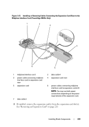
See "Removing an Expansion Card" on the power requirements of the expansion card. 3 If installed, remove the expansion card(s) from the expansion-card slot(s). Installing or Removing Cables Connecting the Expansion-Card Riser to the Midplane Interface Card (PowerEdge M610x Only) 1 2 3 4 7 6 5 1 midplane interface card 3 power cable connecting midplane interface card to expansion-card riser 5 expansion...
See "Removing an Expansion Card" on the power requirements of the expansion card. 3 If installed, remove the expansion card(s) from the expansion-card slot(s). Installing or Removing Cables Connecting the Expansion-Card Riser to the Midplane Interface Card (PowerEdge M610x Only) 1 2 3 4 7 6 5 1 midplane interface card 3 power cable connecting midplane interface card to expansion-card riser 5 expansion...

Fabric OS Administrator’s Guide
Page 93
...power required to determine if there will be powered up of a blade, the available power is compared to required power before power is powered on . NOTE Some FRUs in the chassis may change the power computation enough to be powered off when POST or AP initialization is in which the components are powered... interface. For example, a missing blower FRU may use significant power, yet cannot be powered off the chassis is enough power for operation. You must manually power off list is processed until there is required. Enter the slotPowerOff command with the slot number of the port...
...power required to determine if there will be powered up of a blade, the available power is compared to required power before power is powered on . NOTE Some FRUs in the chassis may change the power computation enough to be powered off when POST or AP initialization is in which the components are powered... interface. For example, a missing blower FRU may use significant power, yet cannot be powered off the chassis is enough power for operation. You must manually power off list is processed until there is required. Enter the slotPowerOff command with the slot number of the port...

Technical Guide
Page 32
... server modules. The Server Modules, I /O Module Inlet and IOM Locations PowerEdge M1000e Technical Guide 31 This isolates these components from pre‐heated air, reducing the required airflow consumptions of the subsystems within the M1000e. The air passes through the server modules, through venting holes in the ... in the figure, the front of the fan as compared to the electrical power required to run the fan. The M1000e fan operates at extreme efficiencies which exhaust the air from the chassis. Dell of the system is then drawn into the fans which correlates directly into savings...
... server modules. The Server Modules, I /O Module Inlet and IOM Locations PowerEdge M1000e Technical Guide 31 This isolates these components from pre‐heated air, reducing the required airflow consumptions of the subsystems within the M1000e. The air passes through the server modules, through venting holes in the ... in the figure, the front of the fan as compared to the electrical power required to run the fan. The M1000e fan operates at extreme efficiencies which exhaust the air from the chassis. Dell of the system is then drawn into the fans which correlates directly into savings...


