
Information Update
Page 11
... these blades to configure and operate the CMC module. PowerEdge M610 and M710 blades require CMC firmware version 2.0 or later. Information Update 11 NOTE: See the latest Dell Chassis Management Controller User's Guide at support.dell.com for complete instructions on how to an M1000e enclosure with your local system. If you have the option...
... these blades to configure and operate the CMC module. PowerEdge M610 and M710 blades require CMC firmware version 2.0 or later. Information Update 11 NOTE: See the latest Dell Chassis Management Controller User's Guide at support.dell.com for complete instructions on how to an M1000e enclosure with your local system. If you have the option...

Information Update
Page 17
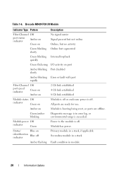
Figure 1-2. Eight ports are external uplink ports, while 16 internal ports provide connectivity to the blades in the enclosure. Mellanox M2401G Infiniband Switch Module 1 2 3 4 5 1 Infiniband ports (8) 3 port activity indicators (8) 5 status/identification indicator 2 port link status indicators (8) 4 module power indicator Information Update 17 Mellanox M2401G Infiniband Switch I/O Module The Mellanox M2401G Infiniband switch I/O module includes 24 4x DDR Infiniband ports.
Figure 1-2. Eight ports are external uplink ports, while 16 internal ports provide connectivity to the blades in the enclosure. Mellanox M2401G Infiniband Switch Module 1 2 3 4 5 1 Infiniband ports (8) 3 port activity indicators (8) 5 status/identification indicator 2 port link status indicators (8) 4 module power indicator Information Update 17 Mellanox M2401G Infiniband Switch I/O Module The Mellanox M2401G Infiniband switch I/O module includes 24 4x DDR Infiniband ports.
Information Update
Page 20
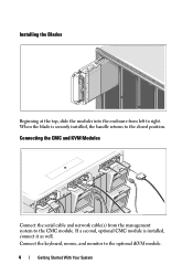
... ports are offline. Module power Off indicator Green Power to the module is exceeded. Module has power. Status/ Blue on identification indicator Blue off or enclosure power is booting being reset, or ports are ready for use. Amber on Module is off Primary module in a stack, if applicable Secondary module in...
... ports are offline. Module power Off indicator Green Power to the module is exceeded. Module has power. Status/ Blue on identification indicator Blue off or enclosure power is booting being reset, or ports are ready for use. Amber on Module is off Primary module in a stack, if applicable Secondary module in...

Getting Started Guide
Page 5
Getting Started With Your System 3 Unpack the System Unpack your system for the first time. Installing the Rails and System in a Rack Assemble the rails and install the system in the rack following procedure, review the safety instructions that came with your enclosure. This section describes the steps required to set up your system and identify each item. Installation and Configuration WARNING: Before performing the following the safety instructions and the rack installation instructions provided with the system.
Getting Started With Your System 3 Unpack the System Unpack your system for the first time. Installing the Rails and System in a Rack Assemble the rails and install the system in the rack following procedure, review the safety instructions that came with your enclosure. This section describes the steps required to set up your system and identify each item. Installation and Configuration WARNING: Before performing the following the safety instructions and the rack installation instructions provided with the system.
Getting Started Guide
Page 6
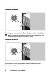
When the blade is installed, connect it as well. Connecting the CMC and KVM Modules Connect the serial cable and network cable(s) from left to right. Connect the keyboard, mouse, and monitor to the closed position. Installing the Blades Beginning at the top, slide the modules into the enclosure from the management system to the CMC module. If a second, optional CMC module is securely installed, the handle returns to the optional iKVM module. 4 Getting Started With Your System
When the blade is installed, connect it as well. Connecting the CMC and KVM Modules Connect the serial cable and network cable(s) from left to right. Connect the keyboard, mouse, and monitor to the closed position. Installing the Blades Beginning at the top, slide the modules into the enclosure from the management system to the CMC module. If a second, optional CMC module is securely installed, the handle returns to the optional iKVM module. 4 Getting Started With Your System
Getting Started Guide
Page 8
NOTE: Once you have connected the system to the power supplies, there may be a minimal delay before you can turn on the blades using the systems management software. 6 Getting Started With Your System Turning On the Blades Press the power button on each blade, or power on your system. The power indicator should light. Turning On the System Press the power button on the enclosure.
NOTE: Once you have connected the system to the power supplies, there may be a minimal delay before you can turn on the blades using the systems management software. 6 Getting Started With Your System Turning On the Blades Press the power button on each blade, or power on your system. The power indicator should light. Turning On the System Press the power button on the enclosure.
Getting Started Guide
Page 12
See www.dell.com/training for updates on configuring the system enclosure and the blades. • Rack Installation Instructions included with your rack solution describes how to install your Hardware Owner's Manual. Other Information You May Need ...
See www.dell.com/training for updates on configuring the system enclosure and the blades. • Rack Installation Instructions included with your rack solution describes how to install your Hardware Owner's Manual. Other Information You May Need ...
Getting Started Guide
Page 20
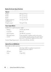
....4 A, 200-240 VAC, 50/60 Hz Optional Avocent iKVM Module Externally accessible connectors USB Two 4-pin, USB 2.0-compliant connectors for 10 ms or less. System Enclosure Specifications Physical Height Width Depth Weight (maximum configuration) Weight (empty) 44.0 cm (17.3 in) 44.7 cm (17.6 in) 75.5 cm (29.7 in) 178.3 kg (392...
....4 A, 200-240 VAC, 50/60 Hz Optional Avocent iKVM Module Externally accessible connectors USB Two 4-pin, USB 2.0-compliant connectors for 10 ms or less. System Enclosure Specifications Physical Height Width Depth Weight (maximum configuration) Weight (empty) 44.0 cm (17.3 in) 44.7 cm (17.6 in) 75.5 cm (29.7 in) 178.3 kg (392...
Getting Started Guide
Page 21
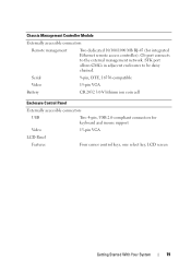
... the external management network. Serial 9-pin, DTE, 16550-compatible Video 15-pin VGA Battery CR 2032 3.0-V lithium ion coin cell Enclosure Control Panel Externally accessible connectors USB Two 4-pin, USB 2.0-compliant connectors for integrated Ethernet remote access controller). Chassis Management Controller Module Externally accessible connectors Remote ...
... the external management network. Serial 9-pin, DTE, 16550-compatible Video 15-pin VGA Battery CR 2032 3.0-V lithium ion coin cell Enclosure Control Panel Externally accessible connectors USB Two 4-pin, USB 2.0-compliant connectors for integrated Ethernet remote access controller). Chassis Management Controller Module Externally accessible connectors Remote ...

Getting Started Guide
Page 22
Environmental NOTE: For additional information about the I/O modules and pass-through modules supported on your enclosure, see dell.com/environmental_datasheets. I/O Module Specifications For information about environmental measurements for specific system configurations, see the Dell PowerEdge M1000e Systems Configuration Guide at 10-250 Hz for 15 min Maximum shock Operating One shock pulse in the positive z...;C (1.8°F) per hour Storage 5% to 95% (noncondensing) Maximum vibration Operating 0.26 Grms at 10-350 Hz for 15 min Storage 1.54 Grms at support.dell.com/manuals.
Environmental NOTE: For additional information about the I/O modules and pass-through modules supported on your enclosure, see dell.com/environmental_datasheets. I/O Module Specifications For information about environmental measurements for specific system configurations, see the Dell PowerEdge M1000e Systems Configuration Guide at 10-250 Hz for 15 min Maximum shock Operating One shock pulse in the positive z...;C (1.8°F) per hour Storage 5% to 95% (noncondensing) Maximum vibration Operating 0.26 Grms at 10-350 Hz for 15 min Storage 1.54 Grms at support.dell.com/manuals.
Dell PowerEdge M1000e Configuration Guide
Page 3
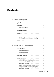
Contents 1 About Your System 7 System Overview 7 LCD Module 11 LCD Module Menus 12 Back-Panel Features 14 Blades 15 CMC Module 22 CMC Daisy Chaining (Enclosure Stacking) . . . . 23 iKVM Switch Module 25 2 Initial System Configuration 27 Before You Begin 27 Power Requirements 27 Network Information 27 Initial Setup Sequence 27 Configuring the CMC 28 Initial CMC Network Configuration 28 Logging in to the CMC Using the Web-Based Interface 31 Adding and Managing CMC Users 32 Configuring iDRAC Networking Using the Web-Based Interface 33 Contents 3
Contents 1 About Your System 7 System Overview 7 LCD Module 11 LCD Module Menus 12 Back-Panel Features 14 Blades 15 CMC Module 22 CMC Daisy Chaining (Enclosure Stacking) . . . . 23 iKVM Switch Module 25 2 Initial System Configuration 27 Before You Begin 27 Power Requirements 27 Network Information 27 Initial Setup Sequence 27 Configuring the CMC 28 Initial CMC Network Configuration 28 Logging in to the CMC Using the Web-Based Interface 31 Adding and Managing CMC Users 32 Configuring iDRAC Networking Using the Web-Based Interface 33 Contents 3
Dell PowerEdge M1000e Configuration Guide
Page 7
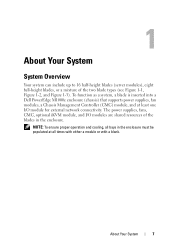
About Your System 7 To function as a system, a blade is inserted into a Dell PowerEdge M1000e enclosure (chassis) that supports power supplies, fan modules, a Chassis Management Controller (CMC) module, and at all bays in the enclosure. 1 About Your System System Overview Your system can include up to 16 half-height ...blades (server modules), eight full-height blades, or a mixture of the blades in the enclosure must be populated at least one I /O modules are shared resources of the two blade types (see Figure 1-1, Figure 1-2, and Figure ...
About Your System 7 To function as a system, a blade is inserted into a Dell PowerEdge M1000e enclosure (chassis) that supports power supplies, fan modules, a Chassis Management Controller (CMC) module, and at all bays in the enclosure. 1 About Your System System Overview Your system can include up to 16 half-height ...blades (server modules), eight full-height blades, or a mixture of the blades in the enclosure must be populated at least one I /O modules are shared resources of the two blade types (see Figure 1-1, Figure 1-2, and Figure ...
Dell PowerEdge M1000e Configuration Guide
Page 10
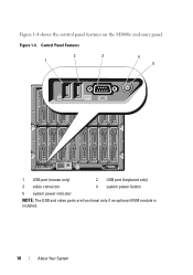
Control Panel Features 2 3 1 4 5 1 USB port (mouse only) 2 USB port (keyboard only) 3 video connector 4 system power button 5 system power indicator NOTE: The USB and video ports are functional only if an optional iKVM module is installed. 10 About Your System Figure 1-4. Figure 1-4 shows the control panel features on the M1000e enclosure panel.
Control Panel Features 2 3 1 4 5 1 USB port (mouse only) 2 USB port (keyboard only) 3 video connector 4 system power button 5 system power indicator NOTE: The USB and video ports are functional only if an optional iKVM module is installed. 10 About Your System Figure 1-4. Figure 1-4 shows the control panel features on the M1000e enclosure panel.

Dell PowerEdge M1000e Configuration Guide
Page 12
... Navigation Keys Keys Left and right arrows Up arrow or down arrow keys to navigate through the options in the enclosure using this button to the LCD Setup Menu, Server Menu, and Enclosure Menu. LCD Setup Menu You can highlight each blade in a menu and to navigate through the options in a menu...
... Navigation Keys Keys Left and right arrows Up arrow or down arrow keys to navigate through the options in the enclosure using this button to the LCD Setup Menu, Server Menu, and Enclosure Menu. LCD Setup Menu You can highlight each blade in a menu and to navigate through the options in a menu...
Dell PowerEdge M1000e Configuration Guide
Page 13
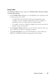
...module is selected, a dialog box displays the current status of the module and any errors present. • In the Enclosure Status dialog box, you can view the enclosure status, any error conditions, and power consumption statistics. • The Network Summary screen lists the IP addresses for the ...CMC, the iDRAC in each component in the enclosure. If a module has errors, it is designated by a gray rectangle. Enclosure Menu The Enclosure Menu includes options for Module Status, Enclosure Status, and Network Summary. • In the Module Status dialog box, ...
...module is selected, a dialog box displays the current status of the module and any errors present. • In the Enclosure Status dialog box, you can view the enclosure status, any error conditions, and power consumption statistics. • The Network Summary screen lists the IP addresses for the ...CMC, the iDRAC in each component in the enclosure. If a module has errors, it is designated by a gray rectangle. Enclosure Menu The Enclosure Menu includes options for Module Status, Enclosure Status, and Network Summary. • In the Module Status dialog box, ...
Dell PowerEdge M1000e Configuration Guide
Page 14
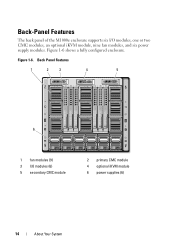
Back Panel Features 1 2 3 4 5 6 1 fan modules (9) 3 I /O modules, one or two CMC modules, an optional iKVM module, nine fan modules, and six power supply modules. Figure 1-6 shows a fully configured enclosure. Figure 1-6. Back-Panel Features The back panel of the M1000e enclosure supports six I /O modules (6) 5 secondary CMC module 2 primary CMC module 4 optional iKVM module 6 power supplies (6) 14 About Your System
Back Panel Features 1 2 3 4 5 6 1 fan modules (9) 3 I /O modules, one or two CMC modules, an optional iKVM module, nine fan modules, and six power supply modules. Figure 1-6 shows a fully configured enclosure. Figure 1-6. Back-Panel Features The back panel of the M1000e enclosure supports six I /O modules (6) 5 secondary CMC module 2 primary CMC module 4 optional iKVM module 6 power supplies (6) 14 About Your System

Dell PowerEdge M1000e Configuration Guide
Page 22
... Gb1 3 link indicator (2) 5 DB-9 serial connector for local configuration 7 primary CMC (CMC 1) 9 status/identification indicator 2 Ethernet connector STK (used for daisy-chaining CMCs in separate enclosures) 4 activity indicator (2) 6 optional secondary CMC (CMC 2) 8 fault indicator 10 power indicator The CMC provides multiple systems management functions for your modular server, including the...
... Gb1 3 link indicator (2) 5 DB-9 serial connector for local configuration 7 primary CMC (CMC 1) 9 status/identification indicator 2 Ethernet connector STK (used for daisy-chaining CMCs in separate enclosures) 4 activity indicator (2) 6 optional secondary CMC (CMC 2) 8 fault indicator 10 power indicator The CMC provides multiple systems management functions for your modular server, including the...

Dell PowerEdge M1000e Configuration Guide
Page 23
...Ethernet port labeled STK is required in port STK on the fourth enclosure in line. Cable all CMC modules in the CMC primary slots together. Primary CMC port GB1 in the adjacent enclosure is valid for up to four M1000e enclosures. In a non-redundant CMC, cable all CMC modules in the... CMC secondary slots together. In a redundant CMC deployment, cable all CMC modules in the adjacent enclosure. NOTE: Do not connect the primary daisy ...
...Ethernet port labeled STK is required in port STK on the fourth enclosure in line. Cable all CMC modules in the CMC primary slots together. Primary CMC port GB1 in the adjacent enclosure is valid for up to four M1000e enclosures. In a non-redundant CMC, cable all CMC modules in the... CMC secondary slots together. In a redundant CMC deployment, cable all CMC modules in the adjacent enclosure. NOTE: Do not connect the primary daisy ...

Dell PowerEdge M1000e Configuration Guide
Page 24
CMC Daisy Chaining-Enclosure With Redundant CMC Modules 1 2 3 1 management network segment 2 CMC1-cable from connector Gb1 to network 3 CMC2-cable from connector Gb1 to network 24 About Your System Figure 1-15.
CMC Daisy Chaining-Enclosure With Redundant CMC Modules 1 2 3 1 management network segment 2 CMC1-cable from connector Gb1 to network 3 CMC2-cable from connector Gb1 to network 24 About Your System Figure 1-15.
Dell PowerEdge M1000e Configuration Guide
Page 25
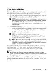
...console session. • The following : • Local iKVM access can be accessed from 640 x 480 at 60 Hz up to disable the sharing of the enclosure, providing front or rear panel KVM functionality, but not at 75 Hz. - Two USB ports for a keyboard, video (monitor), and mouse. NOTE: By ...default (enabled), a console session to a given blade is only used for tiering with Dell and Avocent analog KVM and KVM over IP switches with Analog Rack Interface (ARI) ports, and does not support native KVM over IP. About Your...
...console session. • The following : • Local iKVM access can be accessed from 640 x 480 at 60 Hz up to disable the sharing of the enclosure, providing front or rear panel KVM functionality, but not at 75 Hz. - Two USB ports for a keyboard, video (monitor), and mouse. NOTE: By ...default (enabled), a console session to a given blade is only used for tiering with Dell and Avocent analog KVM and KVM over IP switches with Analog Rack Interface (ARI) ports, and does not support native KVM over IP. About Your...


