View
Page 19
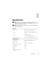
... Mobile Intel GE45 Express chipset 64 bit Dual-channel (2) 64-bit buses 32 bit 16 MB N/A 32 bit Specifications 19 Processor Processor type L1 cache L2 cache Front side bus frequency System Information System chipset Data bus width DRAM bus width...8482; 2 Duo processor Intel Celeron® processor (Socket P) 32 KB per instruction, 32 KB data cache per core 1 MB (Intel Celeron) up to view information about your computer. Specifications NOTE: Offerings may vary by region. NOTE: These specifications apply to both the Dell™ Latitude™ E5400 and E5500 unless indicated otherwise...
... Mobile Intel GE45 Express chipset 64 bit Dual-channel (2) 64-bit buses 32 bit 16 MB N/A 32 bit Specifications 19 Processor Processor type L1 cache L2 cache Front side bus frequency System Information System chipset Data bus width DRAM bus width...8482; 2 Duo processor Intel Celeron® processor (Socket P) 32 KB per instruction, 32 KB data cache per core 1 MB (Intel Celeron) up to view information about your computer. Specifications NOTE: Offerings may vary by region. NOTE: These specifications apply to both the Dell™ Latitude™ E5400 and E5500 unless indicated otherwise...
View
Page 34
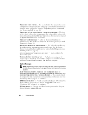
... O F - The time or date stored in the table, see "Contacting Dell" on page 61 for assistance). X : \ I S N O T ...Dell" on page 36). The keyboard controller may be malfunctioning, or a memory module may require recharging. The battery is not listed in the system setup program does not match the system clock. Replace battery. TIME- P L E A S E R U N T H E S YS T E M S E T U P P R O G R A M - U N E X P E C T E D I N T E R R U P T I C A L L Y L O W - System Messages NOTE: If the message you received is running when the message appeared. ALERT! Processor...
... O F - The time or date stored in the table, see "Contacting Dell" on page 61 for assistance). X : \ I S N O T ...Dell" on page 36). The keyboard controller may be malfunctioning, or a memory module may require recharging. The battery is not listed in the system setup program does not match the system clock. Replace battery. TIME- P L E A S E R U N T H E S YS T E M S E T U P P R O G R A M - U N E X P E C T E D I N T E R R U P T I C A L L Y L O W - System Messages NOTE: If the message you received is running when the message appeared. ALERT! Processor...
View
Page 39
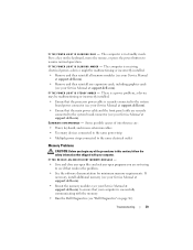
... page 36). I F T H E P O W E R L I G H T I N G A M B E R - The computer is receiving electrical power, a device might be malfunctioning or incorrectly installed. • Ensure that the processor power cable is successfully communicating with your Service Manual at support.dell.com) to ensure that the main power cable and the front panel cable are not using to the system board...
... page 36). I F T H E P O W E R L I G H T I N G A M B E R - The computer is receiving electrical power, a device might be malfunctioning or incorrectly installed. • Ensure that the processor power cable is successfully communicating with your Service Manual at support.dell.com) to ensure that the main power cable and the front panel cable are not using to the system board...
View
Page 65
...communications, 21 display, 22 environmental, 26 keyboard, 23 memory, 20 physical, 25 ports and connectors, 20 processor, 19 system information, 19 touch pad, 23 video, 21 support contacting Dell, 61 information, 54 System Restore, 48 enabling, 50 T telephone numbers, 61 transferring information to a new... computer, 15 troubleshooting, 54 blue screen, 41 computer not responding, 40 Dell Diagnostics, 36 error messages, 29 memory, 39 power, 38 power light conditions, 38 program crashes, 40 programs and Windows compatibility, 41...
...communications, 21 display, 22 environmental, 26 keyboard, 23 memory, 20 physical, 25 ports and connectors, 20 processor, 19 system information, 19 touch pad, 23 video, 21 support contacting Dell, 61 information, 54 System Restore, 48 enabling, 50 T telephone numbers, 61 transferring information to a new... computer, 15 troubleshooting, 54 blue screen, 41 computer not responding, 40 Dell Diagnostics, 36 error messages, 29 memory, 39 power, 38 power light conditions, 38 program crashes, 40 programs and Windows compatibility, 41...
Technical Guide
Page 8
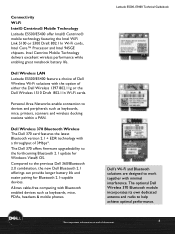
... The Dell 370 card features the latest Bluetooth version 2.1 + EDR technology with the option of document 8 Connectivity Wi-Fi Intel® Centrino® Mobile Technology Latitude E5500/E5400 offer Intel® Centrino® mobile technology featuring the Intel WiFi Link 5100 or 5300 Draft 802.11n Wi-Fi cards, Intel Core™ Processor and...
... The Dell 370 card features the latest Bluetooth version 2.1 + EDR technology with the option of document 8 Connectivity Wi-Fi Intel® Centrino® Mobile Technology Latitude E5500/E5400 offer Intel® Centrino® mobile technology featuring the Intel WiFi Link 5100 or 5300 Draft 802.11n Wi-Fi cards, Intel Core™ Processor and...
Technical Guide
Page 29
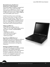
...consumption and scalability to 8GB/sec bandwidth) backwards compatibility with processor and I /O and Graphics Interconnect provide high performance (up to 4GB* of document 29 Intel® Centrino® 2 processor technology helps meet Energy Star™ requirements without sacrificing performance...energy efficiency. New Performance Architecture Intel® Core™ 2 Duo Processor Dell Latitude E5500 and E5400 are equipped with processor and chipset bus architecture. You get powerful mobile dual-core processors with 3MB or 6MB Level 2 cache and up to help increase ...
...consumption and scalability to 8GB/sec bandwidth) backwards compatibility with processor and I /O and Graphics Interconnect provide high performance (up to 4GB* of document 29 Intel® Centrino® 2 processor technology helps meet Energy Star™ requirements without sacrificing performance...energy efficiency. New Performance Architecture Intel® Core™ 2 Duo Processor Dell Latitude E5500 and E5400 are equipped with processor and chipset bus architecture. You get powerful mobile dual-core processors with 3MB or 6MB Level 2 cache and up to help increase ...
Technical Guide
Page 35
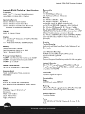
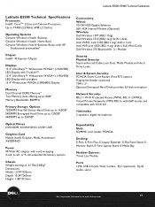
...Depth: 9.61"/244mm Height: 1.46"/37mm Connectivity Wired: 10/100/1000 Gigabit Ethernet 56K v924 Internal Modem (Optional) Wireless: Dell Wireless 1397 (802.11b/g); User & System Security: PCMCIA SmartCard Reader (Post-RTS option) Fingerprint Reader (optional) TPM 1.2*...life battery options Chassis Weight starting at end of document 35 LaLtaittuitduedeE5E550500,0E, 5E4504000TeTcehcnhincaiclaGl Guiudiedbeobookok Latitude E5400 Technical Specifications Processors Intel® CoreTM 2 Duo and Celeron Processors Up to T9400 (2.53GHz, 6MB L2 Cache) Operating Systems Genuine Windows Vista® ...
...Depth: 9.61"/244mm Height: 1.46"/37mm Connectivity Wired: 10/100/1000 Gigabit Ethernet 56K v924 Internal Modem (Optional) Wireless: Dell Wireless 1397 (802.11b/g); User & System Security: PCMCIA SmartCard Reader (Post-RTS option) Fingerprint Reader (optional) TPM 1.2*...life battery options Chassis Weight starting at end of document 35 LaLtaittuitduedeE5E550500,0E, 5E4504000TeTcehcnhincaiclaGl Guiudiedbeobookok Latitude E5400 Technical Specifications Processors Intel® CoreTM 2 Duo and Celeron Processors Up to T9400 (2.53GHz, 6MB L2 Cache) Operating Systems Genuine Windows Vista® ...
Technical Guide
Page 39
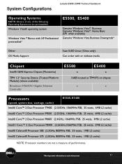
LaLtaittuitduedeE5E550500,0E, 5E4504000TeTcehcnhincaiclaGl Guiudiedbeobookok Latitude E5500 Technical Specifications Processors Intel® CoreTM 2 Duo and Celeron Processors Up to T9400 (2.53GHz, 6MB L2 Cache) Operating Systems Genuine Windows Vista® Business Genuine Windows Vista®...: 10.24"/260mm Height: 1.48"/37.5mm Connectivity Wired: 10/100/1000 Gigabit Ethernet 56K v924 Internal Modem (Optional) Wireless: Dell Wireless 1397 (802.11b/g); Dell Wireless 1510 (802.11a/g/ draft n 2x2); User & System Security: PCMCIA Smart Card Reader (Post RTS option) Fingerprint Reader (optional...
LaLtaittuitduedeE5E550500,0E, 5E4504000TeTcehcnhincaiclaGl Guiudiedbeobookok Latitude E5500 Technical Specifications Processors Intel® CoreTM 2 Duo and Celeron Processors Up to T9400 (2.53GHz, 6MB L2 Cache) Operating Systems Genuine Windows Vista® Business Genuine Windows Vista®...: 10.24"/260mm Height: 1.48"/37.5mm Connectivity Wired: 10/100/1000 Gigabit Ethernet 56K v924 Internal Modem (Optional) Wireless: Dell Wireless 1397 (802.11b/g); Dell Wireless 1510 (802.11a/g/ draft n 2x2); User & System Security: PCMCIA Smart Card Reader (Post RTS option) Fingerprint Reader (optional...
Technical Guide
Page 41
... Platform Module) (where available) Broadcom 5756/5761 Gigabit Ethernet Controller E5500 E5400 x x 16KB located at TPM1P2 on chipset x x Processors (speed, system bus, wattage, cache) E5500, E5400 Intel® Core™ 2 Duo Processor T9400 (2.53GHz, 1066MHz FSB, 35 watts, 6MB L2 cache) ...; Celeron® Processor 575 (2.0GHz, 800MHz FSB, 35 watts, 1MB L2 cache) NOTE: Processor numbers are not a measure of performance. *See important information at end of the following Operating Systems to be preinstalled. System Configurations Latitude E5500, E5400LaTtietucdheniEc5a5l 0G0u,...
... Platform Module) (where available) Broadcom 5756/5761 Gigabit Ethernet Controller E5500 E5400 x x 16KB located at TPM1P2 on chipset x x Processors (speed, system bus, wattage, cache) E5500, E5400 Intel® Core™ 2 Duo Processor T9400 (2.53GHz, 1066MHz FSB, 35 watts, 6MB L2 cache) ...; Celeron® Processor 575 (2.0GHz, 800MHz FSB, 35 watts, 1MB L2 cache) NOTE: Processor numbers are not a measure of performance. *See important information at end of the following Operating Systems to be preinstalled. System Configurations Latitude E5500, E5400LaTtietucdheniEc5a5l 0G0u,...
Service Manual
Page 1
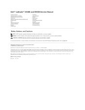
Dell™ Latitude™ E5400 and E5500 Service Manual Troubleshooting Working on Your Computer Bottom of the Base Assembly Hard Drive Wireless Local Area Network (WLAN) Card Modem Card Fan Processor Heat Sink Processor Module Memory Hinge Cover Keyboard LED Dashboard Display Optical Drive Palm Rest System Board Assembly I/O Card Speaker Assembly Coin-Cell Battery Flashing...
Dell™ Latitude™ E5400 and E5500 Service Manual Troubleshooting Working on Your Computer Bottom of the Base Assembly Hard Drive Wireless Local Area Network (WLAN) Card Modem Card Fan Processor Heat Sink Processor Module Memory Hinge Cover Keyboard LED Dashboard Display Optical Drive Palm Rest System Board Assembly I/O Card Speaker Assembly Coin-Cell Battery Flashing...
Service Manual
Page 4
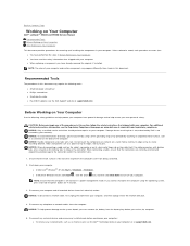
... to servicing that shipped with locking tabs, press inward on the locking tabs to Contents Page Working on Your Computer Dell™ Latitude™ E5400 and E5500 Service Manual Recommended Tools Before Working on Your Computer After Working on the back of the procedures in this section, ...follow the safety instructions that is not authorized by Dell is off your computer. CAUTION: Before you cannot shut down your computer. Hold a card by its edges or by its metal mounting bracket. Hold a component such as a processor by its edges, not by its pins. Ensure that :...
... to servicing that shipped with locking tabs, press inward on the locking tabs to Contents Page Working on Your Computer Dell™ Latitude™ E5400 and E5500 Service Manual Recommended Tools Before Working on Your Computer After Working on the back of the procedures in this section, ...follow the safety instructions that is not authorized by Dell is off your computer. CAUTION: Before you cannot shut down your computer. Hold a card by its edges or by its metal mounting bracket. Hold a component such as a processor by its edges, not by its pins. Ensure that :...
Service Manual
Page 10
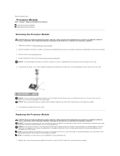
...Processor Module Dell™ Latitude™ E5400 and E5500 Service Manual Removing the Processor Module Replacing the Processor Module Removing the Processor Module CAUTION: Before you have completed the removal procedure first. 1. For additional safety best practices information, see the Regulatory Compliance Homepage on Your Computer. 2. Remove the fan (see Removing the Processor...your skin can result in Before Working on www.dell.com at : www.dell.com/regulatory_compliance. A processor module that is perpendicular to the processor when turning the cam screw. 5. Follow the ...
...Processor Module Dell™ Latitude™ E5400 and E5500 Service Manual Removing the Processor Module Replacing the Processor Module Removing the Processor Module CAUTION: Before you have completed the removal procedure first. 1. For additional safety best practices information, see the Regulatory Compliance Homepage on Your Computer. 2. Remove the fan (see Removing the Processor...your skin can result in Before Working on www.dell.com at : www.dell.com/regulatory_compliance. A processor module that is perpendicular to the processor when turning the cam screw. 5. Follow the ...
Service Manual
Page 11
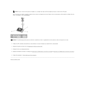
...processor module to Contents Page Replace the fan (see Replacing the Processor Heat Sink). 4. Replace the processor heat sink (see Replacing the Fan). 5. NOTE: The pin-1 corner of the processor... module has a triangle that it is properly seated, all four corners are higher than the others, the module is not seated properly. 1 ZIF-socket cam screw 2 ZIF socket 3 pin-1 corner NOTICE: To avoid damage to the processor..., hold the screwdriver so that aligns with the triangle on Your Computer. When the processor module is perpendicular to the processor when ...
...processor module to Contents Page Replace the fan (see Replacing the Processor Heat Sink). 4. Replace the processor heat sink (see Replacing the Fan). 5. NOTE: The pin-1 corner of the processor... module has a triangle that it is properly seated, all four corners are higher than the others, the module is not seated properly. 1 ZIF-socket cam screw 2 ZIF socket 3 pin-1 corner NOTICE: To avoid damage to the processor..., hold the screwdriver so that aligns with the triangle on Your Computer. When the processor module is perpendicular to the processor when ...
Service Manual
Page 12
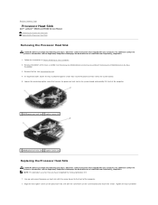
... assumes that you begin the following procedure, follow the safety instructions that secures the processor heat sink to Contents Page Processor Heat Sink Dell™ Latitude™ E5400 and E5500 Service Manual Removing the Processor Heat Sink Replacing the Processor Heat Sink Removing the Processor Heat Sink CAUTION: Before you have completed the removal procedure first. 1. Tighten the...
... assumes that you begin the following procedure, follow the safety instructions that secures the processor heat sink to Contents Page Processor Heat Sink Dell™ Latitude™ E5400 and E5500 Service Manual Removing the Processor Heat Sink Replacing the Processor Heat Sink Removing the Processor Heat Sink CAUTION: Before you have completed the removal procedure first. 1. Tighten the...
Service Manual
Page 34
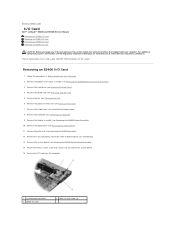
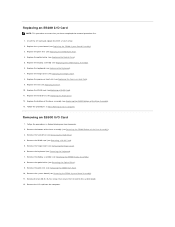
... drive (see Removing the Keyboard). 9. Remove the keyboard (see Removing the Hard Drive). 4. Remove the fan (see Processor Heat Sink). 7. Remove the processor heat sink (see Removing the Fan). 6. For additional safety best practices information, see Removing the E5400 Bottom of the...screw that shipped with your computer. Back to Contents Page I/O Card Dell™ Latitude™ E5400 and E5500 Service Manual Removing an E5400 I/O Card Replacing an E5400 I/O Card Removing an E5500 I/O Card Replacing an E5500 I/O Card CAUTION: Before you begin any of the Base Assembly). 3....
... drive (see Removing the Keyboard). 9. Remove the keyboard (see Removing the Hard Drive). 4. Remove the fan (see Processor Heat Sink). 7. Remove the processor heat sink (see Removing the Fan). 6. For additional safety best practices information, see Removing the E5400 Bottom of the...screw that shipped with your computer. Back to Contents Page I/O Card Dell™ Latitude™ E5400 and E5500 Service Manual Removing an E5400 I/O Card Replacing an E5400 I/O Card Removing an E5500 I/O Card Replacing an E5500 I/O Card CAUTION: Before you begin any of the Base Assembly). 3....
Service Manual
Page 35
Replace the hinge cover (see Replacing the Processor Heat Sink). 9. Replace the processor heat sink (see Replacing the Hinge Cover). 8. Replace the bottom of the base assembly (see Removing the E5400 Bottom of the Base Assembly). 13. ...the E5400 Bottom of the Base Assembly). 3. Remove the keyboard (see Replacing the Optical Drive). 5. Replace the optical drive (see Removing the Keyboard). 7. Removing an E5500 I /O card from the computer. Follow the procedures in After Working on Your Computer. 2. Remove the WLAN card (see Removing the Optical Drive). 9. Remove the optical...
Replace the hinge cover (see Replacing the Processor Heat Sink). 9. Replace the processor heat sink (see Replacing the Hinge Cover). 8. Replace the bottom of the base assembly (see Removing the E5400 Bottom of the Base Assembly). 13. ...the E5400 Bottom of the Base Assembly). 3. Remove the keyboard (see Replacing the Optical Drive). 5. Replace the optical drive (see Removing the Keyboard). 7. Removing an E5500 I /O card from the computer. Follow the procedures in After Working on Your Computer. 2. Remove the WLAN card (see Removing the Optical Drive). 9. Remove the optical...

Service Manual
Page 40
...the display assembly (see Replacing the Fan). 12. Removing the E5500 LED Dashboard CAUTION: Before you begin any of the procedures in After Working on www.dell.com at : www.dell.com/regulatory_compliance. Replace the processor heat sink (see Replacing the Hinge Cover). 10. Replace the ...hinge cover (see Replacing the Processor Heat Sink). 11. 4. For additional safety best practices ...
...the display assembly (see Replacing the Fan). 12. Removing the E5500 LED Dashboard CAUTION: Before you begin any of the procedures in After Working on www.dell.com at : www.dell.com/regulatory_compliance. Replace the processor heat sink (see Replacing the Hinge Cover). 10. Replace the ...hinge cover (see Replacing the Processor Heat Sink). 11. 4. For additional safety best practices ...
Service Manual
Page 49
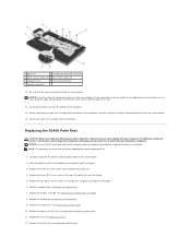
...free. 13. Replace the optical drive (Replacing the Optical Drive). 7. Replace the three M2 x 3-mm screws at : www.dell.com/regulatory_compliance. Replacing the E5400 Palm Rest CAUTION: Before you begin the following procedure, follow the safety instructions that you encounter ... the computer. Replace the fan (see Replacing the E5400 Display Assembly). 8. Replace the keyboard (see Replacing the Processor Heat Sink). 11. Replace the processor heat sink (see Replacing the Keyboard). 9. Before separating the palm rest assembly from the bottom of the computer ...
...free. 13. Replace the optical drive (Replacing the Optical Drive). 7. Replace the three M2 x 3-mm screws at : www.dell.com/regulatory_compliance. Replacing the E5400 Palm Rest CAUTION: Before you begin the following procedure, follow the safety instructions that you encounter ... the computer. Replace the fan (see Replacing the E5400 Display Assembly). 8. Replace the keyboard (see Replacing the Processor Heat Sink). 11. Replace the processor heat sink (see Replacing the Keyboard). 9. Before separating the palm rest assembly from the bottom of the computer ...
Service Manual
Page 53
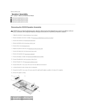
...assembly. 1 left speaker assemblies to Contents Page Speaker Assembly Dell™ Latitude™ E5400 and E5500 Service Manual Removing the E5400 Speaker Assembly Replacing the E5400 Speaker Assembly Removing the E5500 Speaker Assembly Replacing the E5500 Speaker Assembly Removing the E5400 Speaker Assembly CAUTION: Before you... bottom of the base assembly (see Removing the Optical Drive). 11. Remove the hinge cover (see Replacing the Processor Heat Sink). 7. Replace the processor heat sink (see Removing the Hinge Cover). 8. Back to the base of the computer. 15. Carefully remove ...
...assembly. 1 left speaker assemblies to Contents Page Speaker Assembly Dell™ Latitude™ E5400 and E5500 Service Manual Removing the E5400 Speaker Assembly Replacing the E5400 Speaker Assembly Removing the E5500 Speaker Assembly Replacing the E5500 Speaker Assembly Removing the E5400 Speaker Assembly CAUTION: Before you... bottom of the base assembly (see Removing the Optical Drive). 11. Remove the hinge cover (see Replacing the Processor Heat Sink). 7. Replace the processor heat sink (see Removing the Hinge Cover). 8. Back to the base of the computer. 15. Carefully remove ...
Service Manual
Page 54
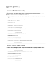
...Compliance Homepage on www.dell.com at : www.dell.com/regulatory_compliance. For additional safety best practices information, see Replacing the Hinge Cover). 11. Remove the fan (see Replacing the Processor Heat Sink). 12. Replace the touch pad cover. 5. Replace the processor heat sink (see ...Removing the Fan). 6. Replace the fan (see Replacing the E5400 Bottom of the Base Assembly). 16. Replace the bottom of the computer. 3. Removing the E5500 Speaker Assembly CAUTION: Before you begin the...
...Compliance Homepage on www.dell.com at : www.dell.com/regulatory_compliance. For additional safety best practices information, see Replacing the Hinge Cover). 11. Remove the fan (see Replacing the Processor Heat Sink). 12. Replace the touch pad cover. 5. Replace the processor heat sink (see ...Removing the Fan). 6. Replace the fan (see Replacing the E5400 Bottom of the Base Assembly). 16. Replace the bottom of the computer. 3. Removing the E5500 Speaker Assembly CAUTION: Before you begin the...


