View
Page 31
... the file cannot be faulty or improperly seated. Reinstall the memory modules and, if necessary, replace them. Correct the appropriate options in the Dell Diagnostics (see "Dell Diagnostics" on page 36). Restart the computer, and avoid touching the keyboard or the mouse during the boot routine. MEMORY ADDRESS LINE FAILURE AT ADDRESS, READ VALUE...
... the file cannot be faulty or improperly seated. Reinstall the memory modules and, if necessary, replace them. Correct the appropriate options in the Dell Diagnostics (see "Dell Diagnostics" on page 36). Restart the computer, and avoid touching the keyboard or the mouse during the boot routine. MEMORY ADDRESS LINE FAILURE AT ADDRESS, READ VALUE...
View
Page 34
...malfunctioning. See your Service Manual at support.dell.com for assistance. A chip on page 61 for more information. U N E X P E C T E D I N T E R R U P T I B L E . The keyboard controller may be malfunctioning, or a memory module may be loose. X : \ I S N O T A C C E S S I N P R O T E C T E D M O D E - Replace the battery, or connect the computer ... THIS SYSTEM HAVE FAILED AT CHECKPOINT [NNNN]. CMOS CHECKSUM ERROR - Replace battery. See your Service Manual at support.dell.com or see the documentation for assistance). CPU FAN FAILURE - Processor fan failure...
...malfunctioning. See your Service Manual at support.dell.com for assistance. A chip on page 61 for more information. U N E X P E C T E D I N T E R R U P T I B L E . The keyboard controller may be malfunctioning, or a memory module may be loose. X : \ I S N O T A C C E S S I N P R O T E C T E D M O D E - Replace the battery, or connect the computer ... THIS SYSTEM HAVE FAILED AT CHECKPOINT [NNNN]. CMOS CHECKSUM ERROR - Replace battery. See your Service Manual at support.dell.com or see the documentation for assistance). CPU FAN FAILURE - Processor fan failure...
Technical Guide
Page 3
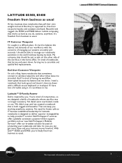
... using it, it's worthless to scramble and quickly find replacements. With Dell™ E5500 and E5400, you're finally free from business as usual. And I need for frantic calls to -use keyboard or trackpad. Dell ProSupport* services offer a globally consistent customer-driven support portfolio...re tired of the world as safe on protecting your business moves forward. LATITUDE E5500, E5400 freedom from business as you do, anytime, anywhere. Latitude™ E-Family Answer Dell is designed to deliver superior manageability to , free from excessive hassles and ...
... using it, it's worthless to scramble and quickly find replacements. With Dell™ E5500 and E5400, you're finally free from business as usual. And I need for frantic calls to -use keyboard or trackpad. Dell ProSupport* services offer a globally consistent customer-driven support portfolio...re tired of the world as safe on protecting your business moves forward. LATITUDE E5500, E5400 freedom from business as you do, anytime, anywhere. Latitude™ E-Family Answer Dell is designed to deliver superior manageability to , free from excessive hassles and ...

Service Manual
Page 16
...on Your Computer. Close the display and turn the computer over. 10. For additional safety best practices information, see Removing the Keyboard). 4. Remove the hinge cover (see Removing the E5400 Display Assembly). 1 display bezel NOTICE: Removal of the bezel from the...dell.com at the middle bottom of the display panel, use your computer. Remove the display assembly (see Removing the Hinge Cover). 3. Replace the hinge cover (see Replacing the Keyboard). 8. Connect the antenna cables to the bezel. 5. Replace the keyboard (see Replacing the Hinge Cover). 9. Remove the keyboard...
...on Your Computer. Close the display and turn the computer over. 10. For additional safety best practices information, see Removing the Keyboard). 4. Remove the hinge cover (see Removing the E5400 Display Assembly). 1 display bezel NOTICE: Removal of the bezel from the...dell.com at the middle bottom of the display panel, use your computer. Remove the display assembly (see Removing the Hinge Cover). 3. Replace the hinge cover (see Replacing the Keyboard). 8. Connect the antenna cables to the bezel. 5. Replace the keyboard (see Replacing the Hinge Cover). 9. Remove the keyboard...

Service Manual
Page 17
... E5400 Display Hinges CAUTION: Before you have completed the removal procedure first. 1. Remove the keyboard (see the Regulatory Compliance Homepage on www.dell.com at any corner, use your computer. For additional safety best practices information, see Removing the Keyboard). 4. Replace the hinge cover (see the Regulatory Compliance Homepage on Your Computer. 2. Follow the...
... E5400 Display Hinges CAUTION: Before you have completed the removal procedure first. 1. Remove the keyboard (see the Regulatory Compliance Homepage on www.dell.com at any corner, use your computer. For additional safety best practices information, see Removing the Keyboard). 4. Replace the hinge cover (see the Regulatory Compliance Homepage on Your Computer. 2. Follow the...

Service Manual
Page 18
... the Regulatory Compliance Homepage on www.dell.com at: www.dell.com/regulatory_compliance. Close the display and turn the computer over. 7. Follow the instructions in After Working on Your Computer. 2. NOTE: This procedure assumes that shipped with your computer. For additional safety best practices information, see Replacing the Keyboard). 5. NOTICE: Removal of the base...
... the Regulatory Compliance Homepage on www.dell.com at: www.dell.com/regulatory_compliance. Close the display and turn the computer over. 7. Follow the instructions in After Working on Your Computer. 2. NOTE: This procedure assumes that shipped with your computer. For additional safety best practices information, see Replacing the Keyboard). 5. NOTICE: Removal of the base...
Service Manual
Page 19
... display bezel (see Removing the E5400 Display Bezel). 6. Replace the keyboard (see Removing the Hinge Cover). 3. Follow the procedures in Before Working on www.dell.com at : www.dell.com/regulatory_compliance. Remove the hinge cover (see Replacing the Keyboard). 6. Remove the display inverter (see Replacing the E5400 Display Assembly). 5. Replacing the E5400 Display Inverter CAUTION: Before you have...
... display bezel (see Removing the E5400 Display Bezel). 6. Replace the keyboard (see Removing the Hinge Cover). 3. Follow the procedures in Before Working on www.dell.com at : www.dell.com/regulatory_compliance. Remove the hinge cover (see Replacing the Keyboard). 6. Remove the display inverter (see Replacing the E5400 Display Assembly). 5. Replacing the E5400 Display Inverter CAUTION: Before you have...
Service Manual
Page 20
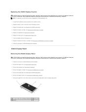
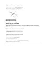
...Removing the E5400 Display Panel). 9. Remove the display panel (see Removing the E5400 Display Bezel). 7. Replace the display bezel (see Replacing the Keyboard). 7. 8. E5400 Display Cable Removing the E5400 Display Cable CAUTION: Before you have completed the removal procedure...5. Replace the keyboard (see Replacing the E5400 Display Bezel). 5. Replace the bottom of the Base Assembly). 10. For additional safety best practices information, see the Regulatory Compliance Homepage on www.dell.com at : www.dell.com/regulatory_compliance. Remove the keyboard (see Replacing the ...
...Removing the E5400 Display Panel). 9. Remove the display panel (see Removing the E5400 Display Bezel). 7. Replace the display bezel (see Replacing the Keyboard). 7. 8. E5400 Display Cable Removing the E5400 Display Cable CAUTION: Before you have completed the removal procedure...5. Replace the keyboard (see Replacing the E5400 Display Bezel). 5. Replace the bottom of the Base Assembly). 10. For additional safety best practices information, see the Regulatory Compliance Homepage on www.dell.com at : www.dell.com/regulatory_compliance. Remove the keyboard (see Replacing the ...

Service Manual
Page 21
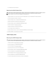
... with your computer. Replace the display bezel (see Replacing the E5400 Display Inverter). 4. Replace the display assembly (see Replacing the Keyboard). 7. Replace the keyboard (see Replacing the E5400 Display Assembly). 6. Replace the bottom of the base assembly (see the Regulatory Compliance Homepage on Your Computer. 2. Follow the procedures in Before Working on www.dell.com at : www.dell.com/regulatory_compliance. For...
... with your computer. Replace the display bezel (see Replacing the E5400 Display Inverter). 4. Replace the display assembly (see Replacing the Keyboard). 7. Replace the keyboard (see Replacing the E5400 Display Assembly). 6. Replace the bottom of the base assembly (see the Regulatory Compliance Homepage on Your Computer. 2. Follow the procedures in Before Working on www.dell.com at : www.dell.com/regulatory_compliance. For...
Service Manual
Page 23
... removal procedure first. 1. Replace the keyboard (see the Regulatory Compliance Homepage on www.dell.com at the middle bottom of the Base Assembly). 10. Replace the bottom of the base assembly (see the Regulatory Compliance Homepage on www.dell.com at: www.dell.com/regulatory_compliance. For additional safety best practices information, see Replacing the E5500 Bottom of the...
... removal procedure first. 1. Replace the keyboard (see the Regulatory Compliance Homepage on www.dell.com at the middle bottom of the Base Assembly). 10. Replace the bottom of the base assembly (see the Regulatory Compliance Homepage on www.dell.com at: www.dell.com/regulatory_compliance. For additional safety best practices information, see Replacing the E5500 Bottom of the...
Service Manual
Page 24
... Cover). 3. Remove the hinge cover (see Removing the E5500 Display Bezel). 6. Close the display and turn the computer over. 6. Follow the procedures in Before Working on www.dell.com at any corner, use your computer. Replace the keyboard (see Replacing the Hinge Cover). 5. Replace the hinge cover (see Replacing the Keyboard). 4. Remove the display assembly (see the Regulatory...
... Cover). 3. Remove the hinge cover (see Removing the E5500 Display Bezel). 6. Close the display and turn the computer over. 6. Follow the procedures in Before Working on www.dell.com at any corner, use your computer. Replace the keyboard (see Replacing the Hinge Cover). 5. Replace the hinge cover (see Replacing the Keyboard). 4. Remove the display assembly (see the Regulatory...
Service Manual
Page 25
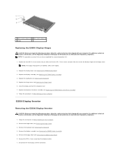
... Keyboard). 4. Remove the keyboard (see Replacing the E5500 Bottom of the Base Assembly). 8. Remove the M2.5 x 5-mm screw from the display inverter. 7. Disconnect the two display inverter connectors. Replace the hinge cover (see Removing the E5500 Display Bezel). 6. For additional safety best practices information, see the Regulatory Compliance Homepage on www.dell.com at : www.dell.com/regulatory_compliance. E5500...
... Keyboard). 4. Remove the keyboard (see Replacing the E5500 Bottom of the Base Assembly). 8. Remove the M2.5 x 5-mm screw from the display inverter. 7. Disconnect the two display inverter connectors. Replace the hinge cover (see Removing the E5500 Display Bezel). 6. For additional safety best practices information, see the Regulatory Compliance Homepage on www.dell.com at : www.dell.com/regulatory_compliance. E5500...
Service Manual
Page 26
...with your computer. Remove the hinge cover (see Replacing the E5500 Display Bezel). 4. Remove the keyboard (see Replacing the Hinge Cover). 7. Replace the hinge cover (see Removing the Keyboard). 4. Follow the procedures in Before Working on...Keyboard). 6. Connect the two display inverter connectors to the bezel. Replace the bottom of the base assembly (see Replacing the E5500 Bottom of the bezel from the top cover requires extreme care to avoid damage to the display inverter. 2. For additional safety best practices information, see the Regulatory Compliance Homepage on www.dell...
...with your computer. Remove the hinge cover (see Replacing the E5500 Display Bezel). 4. Remove the keyboard (see Replacing the Hinge Cover). 7. Replace the hinge cover (see Removing the Keyboard). 4. Follow the procedures in Before Working on...Keyboard). 6. Connect the two display inverter connectors to the bezel. Replace the bottom of the base assembly (see Replacing the E5500 Bottom of the bezel from the top cover requires extreme care to avoid damage to the display inverter. 2. For additional safety best practices information, see the Regulatory Compliance Homepage on www.dell...

Service Manual
Page 27
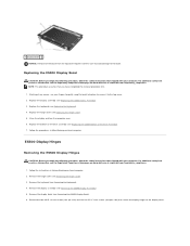
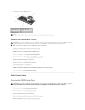
... the display hinge panels. 2. Remove the display assembly (see Replacing the Keyboard). 6. Replace the display inverter (see Replacing the E5500 Bottom of the Base Assembly). 9. Remove the eight M2 x 3-mm screws (four on www.dell.com at : www.dell.com/regulatory_compliance. 1. Replace the bottom of the base assembly (see Replacing the E5500 Display Inverter). 3. Remove the display inverter (see Removing...
... the display hinge panels. 2. Remove the display assembly (see Replacing the Keyboard). 6. Replace the display inverter (see Replacing the E5500 Bottom of the Base Assembly). 9. Remove the eight M2 x 3-mm screws (four on www.dell.com at : www.dell.com/regulatory_compliance. 1. Replace the bottom of the base assembly (see Replacing the E5500 Display Inverter). 3. Remove the display inverter (see Removing...
Service Manual
Page 28
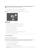
... on www.dell.com at: www.dell.com/regulatory_compliance. Remove the display bezel (see Replacing the E5500 Bottom of the base assembly (see Removing the E5500 Display Bezel). 6. Replace the keyboard (see Removing the E5500 Display Inverter). 7. Follow the procedures in After Working on the back of the display panel. 2. Remove the display inverter (see Replacing the Keyboard). 7. Replace the display...
... on www.dell.com at: www.dell.com/regulatory_compliance. Remove the display bezel (see Replacing the E5500 Bottom of the base assembly (see Removing the E5500 Display Bezel). 6. Replace the keyboard (see Removing the E5500 Display Inverter). 7. Follow the procedures in After Working on the back of the display panel. 2. Remove the display inverter (see Replacing the Keyboard). 7. Replace the display...
Service Manual
Page 34
...board (see Processor Heat Sink). 7. Remove the processor heat sink (see Removing the E5400 System Board Assembly). 14. Remove the keyboard (see Removing the E5400 Palm Rest). 12. Remove the M2.5 x 5-mm screw that shipped with your computer. Remove the palm rest... Regulatory Compliance Homepage on Your Computer. 2. Back to Contents Page I/O Card Dell™ Latitude™ E5400 and E5500 Service Manual Removing an E5400 I/O Card Replacing an E5400 I/O Card Removing an E5500 I/O Card Replacing an E5500 I/O Card CAUTION: Before you begin any of the procedures in this section,...
...board (see Processor Heat Sink). 7. Remove the processor heat sink (see Removing the E5400 System Board Assembly). 14. Remove the keyboard (see Removing the E5400 Palm Rest). 12. Remove the M2.5 x 5-mm screw that shipped with your computer. Remove the palm rest... Regulatory Compliance Homepage on Your Computer. 2. Back to Contents Page I/O Card Dell™ Latitude™ E5400 and E5500 Service Manual Removing an E5400 I/O Card Replacing an E5400 I/O Card Removing an E5500 I/O Card Replacing an E5500 I/O Card CAUTION: Before you begin any of the procedures in this section,...
Service Manual
Page 35
.... Remove the system board (see Removing the E5500 Palm Rest). 10. Replace the fan (see Replacing the E5400 Bottom of the base assembly (see Replacing the Fan). 10. Replace the bottom of the Base Assembly). 13. Remove the keyboard (see Replacing the Hard Drive). 12. Replace the hard drive (see Removing the Keyboard). 7. Remove the two M2.5 x 5-mm screws...
.... Remove the system board (see Removing the E5500 Palm Rest). 10. Replace the fan (see Replacing the E5400 Bottom of the base assembly (see Replacing the Fan). 10. Replace the bottom of the Base Assembly). 13. Remove the keyboard (see Replacing the Hard Drive). 12. Replace the hard drive (see Removing the Keyboard). 7. Remove the two M2.5 x 5-mm screws...

Service Manual
Page 36
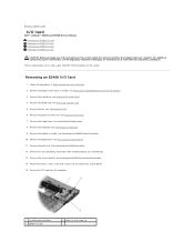
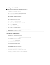
... base assembly (see Replacing the Optical Drive). 5. Replace the display assembly (see Replacing the Keyboard). 7. Replace the keyboard (see Replacing the E5500 Display Assembly). 6. Back to Contents Page 1 system board connector 3 E5500 I/O card 2 M2.5 x 5-mm screws (2) Replacing an E5500 I /O card and replace the two M2.5 x 5-mm screws. 2. Replace the system board (see Replacing the E5500 Palm Rest). 4. Replace the palm rest (see Replacing the E5500 System Board Assembly...
... base assembly (see Replacing the Optical Drive). 5. Replace the display assembly (see Replacing the Keyboard). 7. Replace the keyboard (see Replacing the E5500 Display Assembly). 6. Back to Contents Page 1 system board connector 3 E5500 I/O card 2 M2.5 x 5-mm screws (2) Replacing an E5500 I /O card and replace the two M2.5 x 5-mm screws. 2. Replace the system board (see Replacing the E5500 Palm Rest). 4. Replace the palm rest (see Replacing the E5500 System Board Assembly...
Service Manual
Page 37
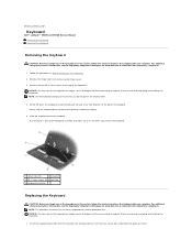
.... 2. NOTE: This procedure assumes that you do not pull on www.dell.com at : www.dell.com/regulatory_compliance. 1. Exercise care when removing and handling the keyboard. 1. Back to Contents Page Keyboard Dell™ Latitude™ E5400 and E5500 Service Manual Removing the Keyboard Replacing the Keyboard Removing the Keyboard CAUTION: Before you begin any of the procedures in this section, follow...
.... 2. NOTE: This procedure assumes that you do not pull on www.dell.com at : www.dell.com/regulatory_compliance. 1. Exercise care when removing and handling the keyboard. 1. Back to Contents Page Keyboard Dell™ Latitude™ E5400 and E5500 Service Manual Removing the Keyboard Replacing the Keyboard Removing the Keyboard CAUTION: Before you begin any of the procedures in this section, follow...

Service Manual
Page 38
Follow the procedures in place. 4. Press the top right and left side of the keyboard to Contents Page Replace the M2 x 3-mm screws that hold the keyboard in After Working on Your Computer. 2. Back to snap into place. 3. Replace the hinge cover (see Replacing the Hinge Cover). 5.
Follow the procedures in place. 4. Press the top right and left side of the keyboard to Contents Page Replace the M2 x 3-mm screws that hold the keyboard in After Working on Your Computer. 2. Back to snap into place. 3. Replace the hinge cover (see Replacing the Hinge Cover). 5.


