Setup Manual
Page 2
... 1: Introduction...3 1.1 Before You Start...3 1.2 Package Checklist...3 1.3 Motherboard Features ...4 1.4 Rear Panel Connectors ...5 1.5 Motherboard Layout ...6 Chapter 2: Hardware Installation...7 2.1 Installing Central Processing Unit (CPU) ...7 2.2 FAN Headers...9 2.3 Installing System Memory...10 2.4 Connectors and Slots ...12 Chapter 3: Headers & Jumpers Setup...14 3.1 How to Setup Jumpers...14 3.2 Detail Settings ...14 Chapter 4: RAID Functions ...21 4.1 Operation System...21...
... 1: Introduction...3 1.1 Before You Start...3 1.2 Package Checklist...3 1.3 Motherboard Features ...4 1.4 Rear Panel Connectors ...5 1.5 Motherboard Layout ...6 Chapter 2: Hardware Installation...7 2.1 Installing Central Processing Unit (CPU) ...7 2.2 FAN Headers...9 2.3 Installing System Memory...10 2.4 Connectors and Slots ...12 Chapter 3: Headers & Jumpers Setup...14 3.1 How to Setup Jumpers...14 3.2 Detail Settings ...14 Chapter 4: RAID Functions ...21 4.1 Operation System...21...
Setup Manual
Page 4
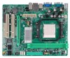
...device Each connector supports 1 SATA devices Supports fron t panel facilities Supports fron t panel audio fun ction Supports CD audio-in function Main Memory Max Memory Capacity 4G B Each DIMM supports 256 MB/512 MB/1GB/ 2GB DDR2 Graphics IDE Integrated in n Force 6100-430 Chipset Integrated IDE Con...terface DDR2 DIMM Slots x 2 Fan Speed Controller ITE's "Smart Guardian" function Dual Channel Mode DDR2 memory modu le Supports DDR2 533 / 667 / 800 Registered DIMM and E CC DIMM is not supported Max Shared Video Memory is 512MB Ultra DMA 33 / 66 / 100 / 133 Bu s Master Mode supports PIO Mode 0...
...device Each connector supports 1 SATA devices Supports fron t panel facilities Supports fron t panel audio fun ction Supports CD audio-in function Main Memory Max Memory Capacity 4G B Each DIMM supports 256 MB/512 MB/1GB/ 2GB DDR2 Graphics IDE Integrated in n Force 6100-430 Chipset Integrated IDE Con...terface DDR2 DIMM Slots x 2 Fan Speed Controller ITE's "Smart Guardian" function Dual Channel Mode DDR2 memory modu le Supports DDR2 533 / 667 / 800 Registered DIMM and E CC DIMM is not supported Max Shared Video Memory is 512MB Ultra DMA 33 / 66 / 100 / 133 Bu s Master Mode supports PIO Mode 0...
Setup Manual
Page 10
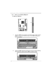
Insert the DIMM vertically and firmly into the slot until the retaining chip snap back in place and the DIMM is properly seated. 10 DIM MA1 DIM MB1 Align a DIMM on the slot such that the notch on the DIMM matches the break on the Slot. 2. Unlock a DIMM slot by pressing the retaining clips outward. Memory Modules 1. Motherboard Manual 2.3 INST ALLING SYST EM MEMORY A.
Insert the DIMM vertically and firmly into the slot until the retaining chip snap back in place and the DIMM is properly seated. 10 DIM MA1 DIM MB1 Align a DIMM on the slot such that the notch on the DIMM matches the break on the Slot. 2. Unlock a DIMM slot by pressing the retaining clips outward. Memory Modules 1. Motherboard Manual 2.3 INST ALLING SYST EM MEMORY A.
Setup Manual
Page 11
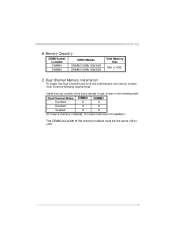
MCP6P-M2 B. Memory Capacity DIMM Socket Location DIMMA1 DIMMB1 DDR2 Module 256MB/512MB/1GB/2GB 256MB/512MB/1GB/2GB Total Memory Size Max is 4GB. Dual Channel Memory installation To trigger the Dual Channel f unction of the same density in pair, shown in the f ollowing table. C. Dual Channel Status Disabled Disabled Enabled DIMMA1 O X O DIMMB1 X O O (O means memory installed, X means memory not installed.) The DRAM bus width of the memory module must meet the following requirements: Install memory module of the motherboard, the memory module must be the same (x8 or x16) 11
MCP6P-M2 B. Memory Capacity DIMM Socket Location DIMMA1 DIMMB1 DDR2 Module 256MB/512MB/1GB/2GB 256MB/512MB/1GB/2GB Total Memory Size Max is 4GB. Dual Channel Memory installation To trigger the Dual Channel f unction of the same density in pair, shown in the f ollowing table. C. Dual Channel Status Disabled Disabled Enabled DIMMA1 O X O DIMMB1 X O O (O means memory installed, X means memory not installed.) The DRAM bus width of the memory module must meet the following requirements: Install memory module of the motherboard, the memory module must be the same (x8 or x16) 11
Setup Manual
Page 26
... fulfilling with the CPU surface. 2. In this case, please double check: 1. Motherboard Manual 5.2 AWARD BIOS BEEP CODE Meaning Video card not found or v ideo card memory bad CPU overheated System will shutdown automatically to relief the CPU protection function. 1. Or you can: 1. CPU fan speed is rotated normally. 3. Wait for seconds...
... fulfilling with the CPU surface. 2. In this case, please double check: 1. Motherboard Manual 5.2 AWARD BIOS BEEP CODE Meaning Video card not found or v ideo card memory bad CPU overheated System will shutdown automatically to relief the CPU protection function. 1. Or you can: 1. CPU fan speed is rotated normally. 3. Wait for seconds...


