Setup Manual
Page 2
... 1.4 Rear Panel Connectors ...5 1.5 Motherboard Layout ...6 Chapter 2: Hardware Installation...7 2.1 Installing Central Processing Unit (CPU) ...7 2.2 FAN Headers...9 2.3 Installing System Memory...10 2.4 Connectors and Slots ...12 Chapter 3: Headers & Jumpers Setup...14 3.1 How to Setup Jumpers...14 3.2 Detail Settings ...14 Chapter 4: RAID Functions ...21 4.1 Operation System...21 4.2 Raid Arrays...21 4.3 How RAID Works...21 Chapter 5: Useful Help ...25 5.1 Driver Installation Note ...25 5.2 Award BIOS Beep Code ...26 5.3 Extra Information...26 5.4 Troubleshooting...27 A ppendencies: SPEC In...
... 1.4 Rear Panel Connectors ...5 1.5 Motherboard Layout ...6 Chapter 2: Hardware Installation...7 2.1 Installing Central Processing Unit (CPU) ...7 2.2 FAN Headers...9 2.3 Installing System Memory...10 2.4 Connectors and Slots ...12 Chapter 3: Headers & Jumpers Setup...14 3.1 How to Setup Jumpers...14 3.2 Detail Settings ...14 Chapter 4: RAID Functions ...21 4.1 Operation System...21 4.2 Raid Arrays...21 4.3 How RAID Works...21 Chapter 5: Useful Help ...25 5.1 Driver Installation Note ...25 5.2 Award BIOS Beep Code ...26 5.3 Extra Information...26 5.4 Troubleshooting...27 A ppendencies: SPEC In...
Setup Manual
Page 3
... air and wate r . „ „ „ 1.2 PACKAGE CHECKLIST HDD Cable X 1 Se rial ATA Cable X 1 Rear I/O Panel for choosing our product. Before you take the mothe rboard out from powe r outle t be fore ope ration. Be fore you start installing the mothe rboard, please make sure you for ATX Case X 1 Installation Guide X 1 Fully Se tup Drive r C D X 1 (full ve rsion manual files inside the case afte r installation.
... air and wate r . „ „ „ 1.2 PACKAGE CHECKLIST HDD Cable X 1 Se rial ATA Cable X 1 Rear I/O Panel for choosing our product. Before you take the mothe rboard out from powe r outle t be fore ope ration. Be fore you start installing the mothe rboard, please make sure you for ATX Case X 1 Installation Guide X 1 Fully Se tup Drive r C D X 1 (full ve rsion manual files inside the case afte r installation.
Setup Manual
Page 4
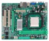
... DDR2 Graphics IDE Integrated in n Force 6100-430 Chipset Integrated IDE Con troller SATA II Integrated Serial ATA Con troller LAN Realtek RTL 8201CL Sound ALC662 PCI slot PCI Express x16 slot Floppy connector Prin ter Port connector IDE Connector SATA Conn ector Fron t Panel Connector Fron t Audio Conn ector CD-in itiatives, Super I/O Provides the most commonly u sed legacy H/W Mon itor Super I/O functionality . Low Pin Coun t In terface DDR2 DIMM Slots x 2 Fan Speed Controller ITE's "Smart Guardian" function Dual Channel Mode DDR2 memory...
... DDR2 Graphics IDE Integrated in n Force 6100-430 Chipset Integrated IDE Con troller SATA II Integrated Serial ATA Con troller LAN Realtek RTL 8201CL Sound ALC662 PCI slot PCI Express x16 slot Floppy connector Prin ter Port connector IDE Connector SATA Conn ector Fron t Panel Connector Fron t Audio Conn ector CD-in itiatives, Super I/O Provides the most commonly u sed legacy H/W Mon itor Super I/O functionality . Low Pin Coun t In terface DDR2 DIMM Slots x 2 Fan Speed Controller ITE's "Smart Guardian" function Dual Channel Mode DDR2 memory...
Setup Manual
Page 5
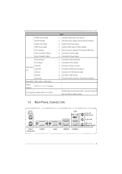
MCP6P-M2 SPEC S/PDIF ou t conn ector CPU Fan header System Fan header CMOS clear header USB conn ector Power Conn ector (24pin) Power Conn ector (4pin) PS/2 Keyboard PS/2 Mouse Back Panel I/O VGA port Serial Port LAN port USB Port Audio Jack Board Size 190 mm(W) x 244 mm(L) Special Features RAID 0 / 1 / 0+1 / 5 support Biostar Reserves the righ t to USB devices Provide Audio-In/Out and microphone connection OS Support Windows 2000 / XP / VISTA 1.4 PS/2 Mouse REAR PANEL CONNECT ORS LAN Li ne In/ Surr ound Li ne Out Mic In...
MCP6P-M2 SPEC S/PDIF ou t conn ector CPU Fan header System Fan header CMOS clear header USB conn ector Power Conn ector (24pin) Power Conn ector (4pin) PS/2 Keyboard PS/2 Mouse Back Panel I/O VGA port Serial Port LAN port USB Port Audio Jack Board Size 190 mm(W) x 244 mm(L) Special Features RAID 0 / 1 / 0+1 / 5 support Biostar Reserves the righ t to USB devices Provide Audio-In/Out and microphone connection OS Support Windows 2000 / XP / VISTA 1.4 PS/2 Mouse REAR PANEL CONNECT ORS LAN Li ne In/ Surr ound Li ne Out Mic In...
Setup Manual
Page 9
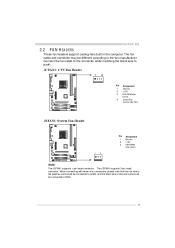
The fan cable and connector may be c onnected to GND. 9 Connect the fan cable to the connector while matching the black wire to the fan manufacturer. JCFAN1: CPU Fan Heade r 1 4 Pin 1 2 3 4 Assignment Ground +12V FAN RPM rate sense Smart Fan Control (By Fan) JSFAN1: System Fan He ader Pin 1 2 3 Assignment Ground +12V FAN RPM rate sense 1 3 Note: The JCFAN1 supports 4-pin head c onnector. When c onnecti ng with wires onto c onnectors, pl ease note that...
The fan cable and connector may be c onnected to GND. 9 Connect the fan cable to the connector while matching the black wire to the fan manufacturer. JCFAN1: CPU Fan Heade r 1 4 Pin 1 2 3 4 Assignment Ground +12V FAN RPM rate sense Smart Fan Control (By Fan) JSFAN1: System Fan He ader Pin 1 2 3 Assignment Ground +12V FAN RPM rate sense 1 3 Note: The JCFAN1 supports 4-pin head c onnector. When c onnecti ng with wires onto c onnectors, pl ease note that...
Setup Manual
Page 11
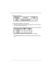
MCP6P-M2 B. Memory Capacity DIMM Socket Location DIMMA1 DIMMB1 DDR2 Module 256MB/512MB/1GB/2GB 256MB/512MB/1GB/2GB Total Memory Size Max is 4GB. Dual Channel Memory installation To trigger the Dual Channel f unction of the motherboard, the memory module must meet the following requirements: Install memory module of the memory module must be the same (x8 or x16) 11 Dual Channel Status Disabled Disabled Enabled DIMMA1 O X O DIMMB1 X O O (O means memory installed, X means memory not installed.) The DRAM bus width of the same density in pair, shown in the f ollowing table. C.
MCP6P-M2 B. Memory Capacity DIMM Socket Location DIMMA1 DIMMB1 DDR2 Module 256MB/512MB/1GB/2GB 256MB/512MB/1GB/2GB Total Memory Size Max is 4GB. Dual Channel Memory installation To trigger the Dual Channel f unction of the motherboard, the memory module must meet the following requirements: Install memory module of the memory module must be the same (x8 or x16) 11 Dual Channel Status Disabled Disabled Enabled DIMMA1 O X O DIMMB1 X O O (O means memory installed, X means memory not installed.) The DRAM bus width of the same density in pair, shown in the f ollowing table. C.
Setup Manual
Page 12
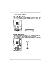
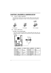
The IDE connector can connect a master and a slave drive, so y ou can connect up to two hard disk driv es. 40 39 2 1 12 This connector supports the prov ided f loppy drive ribbon cables. Motherboard Manual 2.4 CONNECT ORS AND SLOT S The motherboard prov ides a standard floppy disk connector that prov ides PIO Mode 0~4, Bus Master, and Ultra DMA 33/66/100/133 f unctionality. FDD1: Floppy Disk Conne ctor 2 1 34 33 IDE1: Hard Disk Conne ctor The motherboard has a 32-bit Enhanced PCI IDE Controller that supports 360K, 720K, 1.2M, 1.44M and 2.88M floppy disk ty pes.
The IDE connector can connect a master and a slave drive, so y ou can connect up to two hard disk driv es. 40 39 2 1 12 This connector supports the prov ided f loppy drive ribbon cables. Motherboard Manual 2.4 CONNECT ORS AND SLOT S The motherboard prov ides a standard floppy disk connector that prov ides PIO Mode 0~4, Bus Master, and Ultra DMA 33/66/100/133 f unctionality. FDD1: Floppy Disk Conne ctor 2 1 34 33 IDE1: Hard Disk Conne ctor The motherboard has a 32-bit Enhanced PCI IDE Controller that supports 360K, 720K, 1.2M, 1.44M and 2.88M floppy disk ty pes.
Setup Manual
Page 13
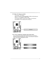
PCI stands f or Peripheral Component Interconnect, and it is designated as 32 bits. PCI1 PCI2 13 PCI-Express supports a raw bit-rate of 8GB/s totally. Maximum theoretical realized bandwidth of 4GB/s simultaneously per direction, f or an aggregate of 2.5GB/s on the data pins. 2X bandwidth ov er the traditional PCI architecture. This PCI slot is a bus standard for expansion cards. PCI-EX16 PCI1~PCI2: Pe riphe ral Component Interconne ct Slots This motherboard is equipped with 2 standard PCI slots. MCP6P-M2 PCI-EX16: PCI-Express x16 Slot PCI-Express 1.0a compliant.
PCI stands f or Peripheral Component Interconnect, and it is designated as 32 bits. PCI1 PCI2 13 PCI-Express supports a raw bit-rate of 8GB/s totally. Maximum theoretical realized bandwidth of 4GB/s simultaneously per direction, f or an aggregate of 2.5GB/s on the data pins. 2X bandwidth ov er the traditional PCI architecture. This PCI slot is a bus standard for expansion cards. PCI-EX16 PCI1~PCI2: Pe riphe ral Component Interconne ct Slots This motherboard is equipped with 2 standard PCI slots. MCP6P-M2 PCI-EX16: PCI-Express x16 Slot PCI-Express 1.0a compliant.
Setup Manual
Page 14
... Speaker HDD LED (+) HDD LED (-) Ground Reset control Functio n Speaker Connector Hard drive LED Reset button Pin 9 10 11 12 13 14 15 16 Assignment N/A N/A N/A Power LED (+) Power LED (+) Power LED (-) Power button Ground Functio n N/A N/A Power LED Power-on , Reset, HDD LED, Power LED, and speaker connection. Pin opened Pin closed Pin1-2 closed 3.2 DET AIL SETT INGS This 16-pin connector includes Power-on button 14 Motherboard Manual CHAPTER 3: HEADERS & JUMPERS SETUP 3.1 HOW T O SET UP JUMPERS The illustration shows how to connect the PC case's front panel switch f unctions...
... Speaker HDD LED (+) HDD LED (-) Ground Reset control Functio n Speaker Connector Hard drive LED Reset button Pin 9 10 11 12 13 14 15 16 Assignment N/A N/A N/A Power LED (+) Power LED (+) Power LED (-) Power button Ground Functio n N/A N/A Power LED Power-on , Reset, HDD LED, Power LED, and speaker connection. Pin opened Pin closed Pin1-2 closed 3.2 DET AIL SETT INGS This 16-pin connector includes Power-on button 14 Motherboard Manual CHAPTER 3: HEADERS & JUMPERS SETUP 3.1 HOW T O SET UP JUMPERS The illustration shows how to connect the PC case's front panel switch f unctions...
Setup Manual
Page 15
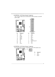
MCP6P-M2 JATXPWR1: ATX Powe r Source Conne ctor This connector allows user to connect 24-pin power connector on the ATX power supply. 13 1 24 Pin 13 14 15 16 17 18 19 20 21 22 23 24 Assignment +3.3V -12V Ground PS_ON Ground Ground Ground NC +5V +5V +5V Ground Pin 1 2 3 4 5 6 7 8 9 10 11 12 12 Assignment +3.3V +3.3V Ground +5V Ground +5V Ground PW_OK Standby Voltage+5V +12V +12V +3.3V JATXPWR4: ATX Powe r Source Conne ctor By connecting this connector, it will provide +12V to CPU power circuit. 1 2 4 3 Pin 1 2 3 4 Assignment +12V +12V Ground Ground 15
MCP6P-M2 JATXPWR1: ATX Powe r Source Conne ctor This connector allows user to connect 24-pin power connector on the ATX power supply. 13 1 24 Pin 13 14 15 16 17 18 19 20 21 22 23 24 Assignment +3.3V -12V Ground PS_ON Ground Ground Ground NC +5V +5V +5V Ground Pin 1 2 3 4 5 6 7 8 9 10 11 12 12 Assignment +3.3V +3.3V Ground +5V Ground +5V Ground PW_OK Standby Voltage+5V +12V +12V +3.3V JATXPWR4: ATX Powe r Source Conne ctor By connecting this connector, it will provide +12V to CPU power circuit. 1 2 4 3 Pin 1 2 3 4 Assignment +12V +12V Ground Ground 15
Setup Manual
Page 16
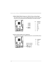
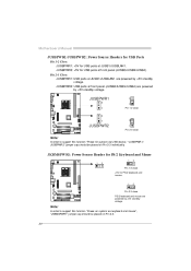
Pin Assignment +5V (fused) +5V (fused) USBUSBUSB+ USB+ Ground Ground Key NC JUSB3 JUSB2 JUSB4 2 1 10 9 1 2 3 4 5 6 7 8 9 10 SATA1~SATA4: Se rial ATA Connectors The motherboard has a PCI to connect additional USB cable on the PC f ront panel, and also can be connected with 4 channels SATA interf ace. SATA3 SATA4 SATA1 SATA2 1 4 7 Pin 1 2 3 4 5 6 7 Assignment Ground T X+ T XGround RXRX+ Ground 16 Motherboard Manual JUSB2/JUSB3/JUSB4: He ade rs for USB 2.0 Ports at Front Panel This header allows user to SATA Controller with internal USB devices, like USB card reader.
Pin Assignment +5V (fused) +5V (fused) USBUSBUSB+ USB+ Ground Ground Key NC JUSB3 JUSB2 JUSB4 2 1 10 9 1 2 3 4 5 6 7 8 9 10 SATA1~SATA4: Se rial ATA Connectors The motherboard has a PCI to connect additional USB cable on the PC f ront panel, and also can be connected with 4 channels SATA interf ace. SATA3 SATA4 SATA1 SATA2 1 4 7 Pin 1 2 3 4 5 6 7 Assignment Ground T X+ T XGround RXRX+ Ground 16 Motherboard Manual JUSB2/JUSB3/JUSB4: He ade rs for USB 2.0 Ports at Front Panel This header allows user to SATA Controller with internal USB devices, like USB card reader.
Setup Manual
Page 17
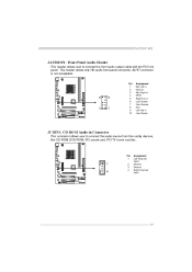
... GPIO Right line in Jack Sense Front Sense Key Left line in Jack Sense JCDIN1: CD-RO M Audio-in Connector This connector allows user to connect the front audio output cable with the PC f ront panel. This header allows only HD audio front panel connector; MCP6P-M2 JAUDIO F1: Front Panel Audio Heade r This header allows user to connect the audio source f rom the v ariaty dev ices, like CD-ROM, DVD-ROM, PCI sound card, PCI TV turner card etc..
... GPIO Right line in Jack Sense Front Sense Key Left line in Jack Sense JCDIN1: CD-RO M Audio-in Connector This connector allows user to connect the front audio output cable with the PC f ront panel. This header allows only HD audio front panel connector; MCP6P-M2 JAUDIO F1: Front Panel Audio Heade r This header allows user to connect the audio source f rom the v ariaty dev ices, like CD-ROM, DVD-ROM, PCI sound card, PCI TV turner card etc..
Setup Manual
Page 18
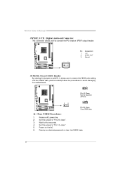
... procedures to connect the PCI bracket SPDIF output header. Pin 1 2 3 Assignment +5V SPDIF_OUT Ground 1 3 JCMO S1: Cle ar CMOS Heade r By placing the jumper on the AC. Set the jumper to "Pin 2-3 close ". Motherboard Manual JSPDIF_O UT1: Digital Audio-out Conne ctor This connector allows user to avoid damaging the motherboard. 1 3 Pin 1-2 Close: Normal Operation (default). 1 3 1 3 Pin 2-3 Close: Clear CMOS data. ※ Clear CMOS Proce dures: 1. 2. 3. 4. 5. 6. Remov e AC power line. Reset y our desired password or clear the CMOS data...
... procedures to connect the PCI bracket SPDIF output header. Pin 1 2 3 Assignment +5V SPDIF_OUT Ground 1 3 JCMO S1: Cle ar CMOS Heade r By placing the jumper on the AC. Set the jumper to "Pin 2-3 close ". Motherboard Manual JSPDIF_O UT1: Digital Audio-out Conne ctor This connector allows user to avoid damaging the motherboard. 1 3 Pin 1-2 Close: Normal Operation (default). 1 3 1 3 Pin 2-3 Close: Clear CMOS data. ※ Clear CMOS Proce dures: 1. 2. 3. 4. 5. 6. Remov e AC power line. Reset y our desired password or clear the CMOS data...
Setup Manual
Page 19
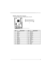
MCP6P-M2 JPRNT1: Printe r Port Connector This header allows you to connector printer on the PC. 2 1 25 Pin 1 2 3 4 5 6 7 8 9 10 11 12 13 Assignment -Strobe -ALF Data 0 -Error Data 1 -Init Data 2 -Scltin Data 3 Ground Data 4 Ground Data 5 Pin 14 15 16 17 18 19 20 21 22 23 24 25 26 Assignment Ground Data 6 Ground Data 7 Ground -ACK Ground Busy Ground PE Ground SCLT Key 19
MCP6P-M2 JPRNT1: Printe r Port Connector This header allows you to connector printer on the PC. 2 1 25 Pin 1 2 3 4 5 6 7 8 9 10 11 12 13 Assignment -Strobe -ALF Data 0 -Error Data 1 -Init Data 2 -Scltin Data 3 Ground Data 4 Ground Data 5 Pin 14 15 16 17 18 19 20 21 22 23 24 25 26 Assignment Ground Data 6 Ground Data 7 Ground -ACK Ground Busy Ground PE Ground SCLT Key 19
Setup Manual
Page 20
... placed on Pi n 2-3. 20 JUSBPWR1 3 1 3 1 3 1 Pin 1-2 close 3 1 Pin 2-3 close PS/2 keyboard and mouse are powered by +5V standby v oltage. Motherboard Manual JUSBPWR1/JUSBPWR2: Powe r Source Heade rs for USB Ports Pin 1-2 Close: JUSBPWR1: +5V for USB ports at f ront panel (JUSB2/JUSB3/JUSB4). Note: In order to support this func tion "Power-on s ystem via U SB device," "JUSBPWR 1/ JUSBPWR 2" jumper c ap s hould be placed on Pi...
... placed on Pi n 2-3. 20 JUSBPWR1 3 1 3 1 3 1 Pin 1-2 close 3 1 Pin 2-3 close PS/2 keyboard and mouse are powered by +5V standby v oltage. Motherboard Manual JUSBPWR1/JUSBPWR2: Powe r Source Heade rs for USB Ports Pin 1-2 Close: JUSBPWR1: +5V for USB ports at f ront panel (JUSB2/JUSB3/JUSB4). Note: In order to support this func tion "Power-on s ystem via U SB device," "JUSBPWR 1/ JUSBPWR 2" jumper c ap s hould be placed on Pi...
Setup Manual
Page 21
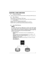
... MCP6P-M2 CHAPTER 4: RAID FUNCTIONS 4.1 O PERAT ION SYST EM z Supports Windows XP Home/Prof essional Edition, and Windows 2000 Prof essional. 4.2 RAID ARRAYS RAID supports the following types of disk capacity. 4.3 HOW RAID 0: RAID WORKS The controller " stripes" data across multiple drives in RAID 0 and RAID 1. This technique reduces overall disk access time and offers high bandwidth. Depending on the system environment. RAID 5: RAID 5 provides fault tolerance and better utilization of RAID arrays: RAID 0: RAID 0 defines a disk striping...
... MCP6P-M2 CHAPTER 4: RAID FUNCTIONS 4.1 O PERAT ION SYST EM z Supports Windows XP Home/Prof essional Edition, and Windows 2000 Prof essional. 4.2 RAID ARRAYS RAID supports the following types of disk capacity. 4.3 HOW RAID 0: RAID WORKS The controller " stripes" data across multiple drives in RAID 0 and RAID 1. This technique reduces overall disk access time and offers high bandwidth. Depending on the system environment. RAID 5: RAID 5 provides fault tolerance and better utilization of RAID arrays: RAID 0: RAID 0 defines a disk striping...
Setup Manual
Page 24
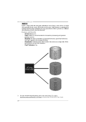
... can be CPU intensiv e. Fault Tolerance: Yes. It writes data and parity blocks across three or more detailed setup information, please refer to the Driver CD, or go to http://www.nvidia.com/object/IO_28159.html to store the data itself. Fault tolerance is placed on a different drive from those used to download the NVIDIA RAID User's Guide. 24...
... can be CPU intensiv e. Fault Tolerance: Yes. It writes data and parity blocks across three or more detailed setup information, please refer to the Driver CD, or go to http://www.nvidia.com/object/IO_28159.html to store the data itself. Fault tolerance is placed on a different drive from those used to download the NVIDIA RAID User's Guide. 24...
Setup Manual
Page 25
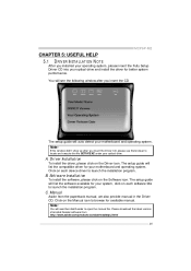
... Manual icon to launch the installation program. MCP6P-M2 CHAPTER 5: USEFUL HELP 5.1 DRIVER INST ALLAT ION NOT E After you installed your operating system, please insert the Fully Setup Driver CD into your motherboard and operating system. Note: If this window didn't show up after you insert the CD The setup guide will list the compatible driver for better system performance. The setup guide will auto detect your optical drive and install...
... Manual icon to launch the installation program. MCP6P-M2 CHAPTER 5: USEFUL HELP 5.1 DRIVER INST ALLAT ION NOT E After you installed your operating system, please insert the Fully Setup Driver CD into your motherboard and operating system. Note: If this window didn't show up after you insert the CD The setup guide will list the compatible driver for better system performance. The setup guide will auto detect your optical drive and install...
Setup Manual
Page 26
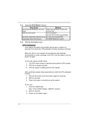
... CPU speed. When the CPU is rotated normally. 3. In this case, please double check: 1. Clear the CMOS data. (See "Close CMOS Header: JCMOS1" section) 2. CPU Overheated 26 Power on again. CPU fan is over heated, the motherboard will shut down automatically Beep Sound One long beep followed by two short beeps High-low siren sound One Short beep when system boot-up the system. Motherboard Manual 5.2 AWARD BIOS BEEP CODE Meaning Video card not found during POST Long beeps every other second No DRAM detected or install...
... CPU speed. When the CPU is rotated normally. 3. In this case, please double check: 1. Clear the CMOS data. (See "Close CMOS Header: JCMOS1" section) 2. CPU Overheated 26 Power on again. CPU fan is over heated, the motherboard will shut down automatically Beep Sound One long beep followed by two short beeps High-low siren sound One Short beep when system boot-up the system. Motherboard Manual 5.2 AWARD BIOS BEEP CODE Meaning Video card not found during POST Long beeps every other second No DRAM detected or install...
Setup Manual
Page 27
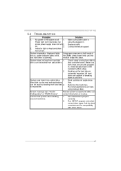
... be used but booting from hard disk 1. Set master/slave jumpers second hard driv e. TROUBLESHOOT ING Probable Solution 1. driv e, can be booted f rom optical driv e. check the driv e type in setup. is spinning. Make sure power cable is in the standard CMOS setup. 2. Contact technical support. 2. System does not boot from hard disk 2. MCP6P-M2 5.4 1. Make sure Conf iguration" or "CMOS Failure." Power light don't illuminate, f an inside power supply does not turn on , power indicator lights are securely plugged in . Keyboard lights Using even...
... be used but booting from hard disk 1. Set master/slave jumpers second hard driv e. TROUBLESHOOT ING Probable Solution 1. driv e, can be booted f rom optical driv e. check the driv e type in setup. is spinning. Make sure power cable is in the standard CMOS setup. 2. Contact technical support. 2. System does not boot from hard disk 2. MCP6P-M2 5.4 1. Make sure Conf iguration" or "CMOS Failure." Power light don't illuminate, f an inside power supply does not turn on , power indicator lights are securely plugged in . Keyboard lights Using even...


