Setup Manual
Page 2
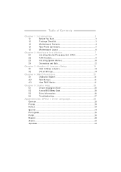
Table of Contents Chapter 1: Introduction...3 1.1 Before You Start...3 1.2 Package Checklist...3 1.3 Motherboard Features ...4 1.4 Rear Panel Connectors ...5 1.5 Motherboard Layout ...6 Chapter 2: Hardware Installation...7 2.1 Installing Central Processing Unit (CPU) ...7 2.2 FAN Headers...9 2.3 Installing System Memory...10 2.4 Connectors and Slots ...12 Chapter 3: Headers & Jumpers Setup...14 3.1 How to Setup Jumpers...14 3.2 Detail Settings ...14 Chapter 4: RAID ...
Table of Contents Chapter 1: Introduction...3 1.1 Before You Start...3 1.2 Package Checklist...3 1.3 Motherboard Features ...4 1.4 Rear Panel Connectors ...5 1.5 Motherboard Layout ...6 Chapter 2: Hardware Installation...7 2.1 Installing Central Processing Unit (CPU) ...7 2.2 FAN Headers...9 2.3 Installing System Memory...10 2.4 Connectors and Slots ...12 Chapter 3: Headers & Jumpers Setup...14 3.1 How to Setup Jumpers...14 3.2 Detail Settings ...14 Chapter 4: RAID ...
Setup Manual
Page 4
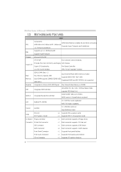
... 1.3 MOT HERBOARD FEAT URES SPEC Socket AM2 AMD 64 Architectu re enables 32 and 64 bit compu ting Supports Hyper Tran sport and Cool= n =Quiet CPU AMD Ath lon 64 / Ath lon 64 FX / Athlon 64 x2 / Sempron processors FSB Chipset Supports up to 3 Gb/s. SATA Version 2.0 specification compliant. 10 / 100...
... 1.3 MOT HERBOARD FEAT URES SPEC Socket AM2 AMD 64 Architectu re enables 32 and 64 bit compu ting Supports Hyper Tran sport and Cool= n =Quiet CPU AMD Ath lon 64 / Ath lon 64 FX / Athlon 64 x2 / Sempron processors FSB Chipset Supports up to 3 Gb/s. SATA Version 2.0 specification compliant. 10 / 100...
Setup Manual
Page 5
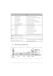
MCP6P-M2 SPEC S/PDIF ou t conn ector CPU Fan header System Fan header CMOS clear header USB conn ector Power Conn ector (24pin) Power Conn ector (4pin) PS/2 Keyboard PS/2 Mouse Back Panel I/O VGA port Serial Port LAN port USB Port Audio Jack Board Size 190 mm(W) x 244 mm(L) Special Features RAID 0 / 1 / 0+1 / 5 support Biostar ... d COM1 VGA USB X2 USBX2 5 x1 x1 x1 x1 x3 x1 x1 x1 x1 x1 x1 x1 x4 x3 Supports digital audio out fun ction CPU Fan power supply (with Smart Fan function) System Fan Power supply Restore CMOS data to factory default Each connector supports 2 fron t panel USB ports ...
MCP6P-M2 SPEC S/PDIF ou t conn ector CPU Fan header System Fan header CMOS clear header USB conn ector Power Conn ector (24pin) Power Conn ector (4pin) PS/2 Keyboard PS/2 Mouse Back Panel I/O VGA port Serial Port LAN port USB Port Audio Jack Board Size 190 mm(W) x 244 mm(L) Special Features RAID 0 / 1 / 0+1 / 5 support Biostar ... d COM1 VGA USB X2 USBX2 5 x1 x1 x1 x1 x3 x1 x1 x1 x1 x1 x1 x1 x4 x3 Supports digital audio out fun ction CPU Fan power supply (with Smart Fan function) System Fan Power supply Restore CMOS data to factory default Each connector supports 2 fron t panel USB ports ...
Setup Manual
Page 7
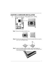
The CPU will fit only in the correct orientation. 7 MCP6P-M2 CHAPTER 2: HARDWARE INSTALLATION 2.1 INST ALLING CENT RAL PROCESSING UNIT (CPU) Step 1: Remove the socket protection cap. Step 2: Pull the lever toward direction A from the socket and then raise the lever up to a 90-degree angle. Step 3: Look for the white triangle on socket, and the gold triangle on CPU should point towards this white triangle.
The CPU will fit only in the correct orientation. 7 MCP6P-M2 CHAPTER 2: HARDWARE INSTALLATION 2.1 INST ALLING CENT RAL PROCESSING UNIT (CPU) Step 1: Remove the socket protection cap. Step 2: Pull the lever toward direction A from the socket and then raise the lever up to a 90-degree angle. Step 3: Look for the white triangle on socket, and the gold triangle on CPU should point towards this white triangle.
Setup Manual
Page 8
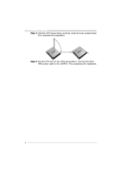
This completes the installation. 8 Step 5: Put the CPU Fan on the CPU and buckle it. Connect the CPU FAN power cable to complete the installation. Motherboard Manual Step 4: Hold the CPU down firmly, and then close the lever toward direct B to the JCFAN1.
This completes the installation. 8 Step 5: Put the CPU Fan on the CPU and buckle it. Connect the CPU FAN power cable to complete the installation. Motherboard Manual Step 4: Hold the CPU down firmly, and then close the lever toward direct B to the JCFAN1.
Setup Manual
Page 9
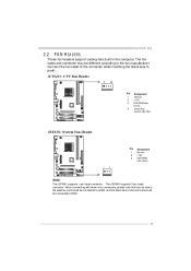
... and s hould be different according to the fan manufacturer. Connect the fan cable to the connector while matching the black wire to GND. 9 MCP6P-M2 2.2 FAN HEADERS These fan headers support cooling-fans built in the computer. The fan cable and connector may be c onnected to pin#1. JCFAN1...: CPU Fan Heade r 1 4 Pin 1 2 3 4 Assignment Ground +12V FAN RPM rate sense Smart Fan Control (By Fan) JSFAN1: System Fan He ader Pin 1 2 3 Assignment Ground ...
... and s hould be different according to the fan manufacturer. Connect the fan cable to the connector while matching the black wire to GND. 9 MCP6P-M2 2.2 FAN HEADERS These fan headers support cooling-fans built in the computer. The fan cable and connector may be c onnected to pin#1. JCFAN1...: CPU Fan Heade r 1 4 Pin 1 2 3 4 Assignment Ground +12V FAN RPM rate sense Smart Fan Control (By Fan) JSFAN1: System Fan He ader Pin 1 2 3 Assignment Ground ...
Setup Manual
Page 15
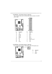
MCP6P-M2 JATXPWR1: ATX Powe r Source Conne ctor This connector allows user to connect 24-pin power connector on the ATX power supply. 13 1 24 Pin 13 14 15 16 17 18 19 20 21 22 23 24 Assignment +3.3V -12V Ground PS_ON Ground Ground Ground NC +5V +5V +5V Ground Pin 1 2 3 4 5 6 7 8 9 10 11 12 12 Assignment +3.3V +3.3V Ground +5V Ground +5V Ground PW_OK Standby Voltage+5V +12V +12V +3.3V JATXPWR4: ATX Powe r Source Conne ctor By connecting this connector, it will provide +12V to CPU power circuit. 1 2 4 3 Pin 1 2 3 4 Assignment +12V +12V Ground Ground 15
MCP6P-M2 JATXPWR1: ATX Powe r Source Conne ctor This connector allows user to connect 24-pin power connector on the ATX power supply. 13 1 24 Pin 13 14 15 16 17 18 19 20 21 22 23 24 Assignment +3.3V -12V Ground PS_ON Ground Ground Ground NC +5V +5V +5V Ground Pin 1 2 3 4 5 6 7 8 9 10 11 12 12 Assignment +3.3V +3.3V Ground +5V Ground +5V Ground PW_OK Standby Voltage+5V +12V +12V +3.3V JATXPWR4: ATX Powe r Source Conne ctor By connecting this connector, it will provide +12V to CPU power circuit. 1 2 4 3 Pin 1 2 3 4 Assignment +12V +12V Ground Ground 15
Setup Manual
Page 24
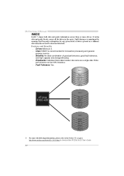
... data is recommended for any given block of good perf ormance, good f ault tolerance, and high capacity and storage efficiency. Write perf ormance can be CPU intensiv e. It writes data and parity blocks across three or more detailed setup information, please refer to the Driver CD, or go to http://www...
... data is recommended for any given block of good perf ormance, good f ault tolerance, and high capacity and storage efficiency. Write perf ormance can be CPU intensiv e. It writes data and parity blocks across three or more detailed setup information, please refer to the Driver CD, or go to http://www...
Setup Manual
Page 26
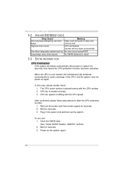
...Wait for seconds. 2. Remove the power cord from power supply for seconds. 3. Power on again. CPU fan is placed evenly with the CPU speed. Wait for seconds, that means the CPU protection function has been activated. Plug in the power cord and boot up No error found during POST ... automatically after power on system for seconds. 3. Clear the CMOS data. (See "Close CMOS Header: JCMOS1" section) 2. CPU Overheated 26 Or you can: 1. CPU fan speed is over heated, the motherboard will shut down automatically Beep Sound One long beep followed by two short beeps High-...
...Wait for seconds. 2. Remove the power cord from power supply for seconds. 3. Power on again. CPU fan is placed evenly with the CPU speed. Wait for seconds, that means the CPU protection function has been activated. Plug in the power cord and boot up No error found during POST ... automatically after power on system for seconds. 3. Clear the CMOS data. (See "Close CMOS Header: JCMOS1" section) 2. CPU Overheated 26 Or you can: 1. CPU fan speed is over heated, the motherboard will shut down automatically Beep Sound One long beep followed by two short beeps High-...


