Setup Manual
Page 14
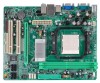
..., Power LED, and speaker connection. When the jumper cap is placed on pins, the jumper is "close", if not, that means the jumper is "open". Motherboard Manual CHAPTER 3: HEADERS & JUMPERS SETUP 3.1 HOW T O SET UP JUMPERS The illustration shows how to connect the PC case's front panel switch f unctions. It allows...
..., Power LED, and speaker connection. When the jumper cap is placed on pins, the jumper is "close", if not, that means the jumper is "open". Motherboard Manual CHAPTER 3: HEADERS & JUMPERS SETUP 3.1 HOW T O SET UP JUMPERS The illustration shows how to connect the PC case's front panel switch f unctions. It allows...
Setup Manual
Page 16
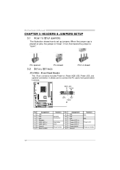
Pin Assignment +5V (fused) +5V (fused) USBUSBUSB+ USB+ Ground Ground Key NC JUSB3 JUSB2 JUSB4 2 1 10 9 1 2 3 4 5 6 7 8 9 10 SATA1~SATA4: Se rial ATA Connectors The motherboard has a PCI to connect additional USB cable on the PC f ront panel, and also can be connected with 4 channels SATA interf ace. Motherboard Manual JUSB2/JUSB3/JUSB4: He ade rs for USB 2.0 Ports at Front Panel This header allows user to SATA Controller with internal USB devices, like USB card reader. SATA3 SATA4 SATA1 SATA2 1 4 7 Pin 1 2 3 4 5 6 7 Assignment Ground T X+ T XGround RXRX+ Ground 16
Pin Assignment +5V (fused) +5V (fused) USBUSBUSB+ USB+ Ground Ground Key NC JUSB3 JUSB2 JUSB4 2 1 10 9 1 2 3 4 5 6 7 8 9 10 SATA1~SATA4: Se rial ATA Connectors The motherboard has a PCI to connect additional USB cable on the PC f ront panel, and also can be connected with 4 channels SATA interf ace. Motherboard Manual JUSB2/JUSB3/JUSB4: He ade rs for USB 2.0 Ports at Front Panel This header allows user to SATA Controller with internal USB devices, like USB card reader. SATA3 SATA4 SATA1 SATA2 1 4 7 Pin 1 2 3 4 5 6 7 Assignment Ground T X+ T XGround RXRX+ Ground 16
Setup Manual
Page 18
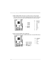
... 6. Power on pin2-3, it allows user to restore the BIOS saf e setting and the CMOS data, please carefully f ollow the procedures to "Pin 2-3 close ". Wait f or f ive seconds. Reset y our desired password or clear the CMOS data. 18 Motherboard Manual JSPDIF_O UT1: Digital Audio-out Conne ...ctor This connector allows user to "Pin 1-2 close ". Set the jumper to connect the PCI bracket SPDIF output header. Remov e AC power ...
... 6. Power on pin2-3, it allows user to restore the BIOS saf e setting and the CMOS data, please carefully f ollow the procedures to "Pin 2-3 close ". Wait f or f ive seconds. Reset y our desired password or clear the CMOS data. 18 Motherboard Manual JSPDIF_O UT1: Digital Audio-out Conne ...ctor This connector allows user to "Pin 1-2 close ". Set the jumper to connect the PCI bracket SPDIF output header. Remov e AC power ...
Setup Manual
Page 24
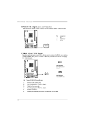
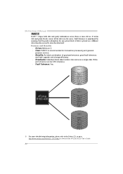
...ormance, good f ault tolerance, and high capacity and storage efficiency. Uses: RAID 5 is placed on a different drive from those used to download the NVIDIA RAID User's Guide. 24 Fault Tolerance: Yes. Dis k 1 DATA 1 DATA 3 PARITY DATA 7 DATA 9 PARITY Dis k 2 nForce 6100-430 DATA 2 PARITY ...PARITY DATA 10 DATA 12 ※ For more drives. Features and Benefits Drives: Minimum 3. Write perf ormance can be CPU intensiv e. Motherboard Manual RAID 5: RAID 5 stripes both data and parity information across all the drives in the array. It writes data and parity blocks across three...
...ormance, good f ault tolerance, and high capacity and storage efficiency. Uses: RAID 5 is placed on a different drive from those used to download the NVIDIA RAID User's Guide. 24 Fault Tolerance: Yes. Dis k 1 DATA 1 DATA 3 PARITY DATA 7 DATA 9 PARITY Dis k 2 nForce 6100-430 DATA 2 PARITY ...PARITY DATA 10 DATA 12 ※ For more drives. Features and Benefits Drives: Minimum 3. Write perf ormance can be CPU intensiv e. Motherboard Manual RAID 5: RAID 5 stripes both data and parity information across all the drives in the array. It writes data and parity blocks across three...


