
Setup Manual
Page 1
...occur in a particular ins tallation. All the brand and produc t names are designed to provide reasonable protec tion against harmful interference in this user's manual is subject to revise this publication, in part or in whole, is no representations or warranties with respec t to radio communications . The content of... of the FCC Rules . T his equipment generates , uses , and c an radiate radio frequency energy and, if not ins talled and used in writing. MCP6P-M2 Setup Manual FCC Information and Copyright This equipment has been tes ted and found in a residential installation.
...occur in a particular ins tallation. All the brand and produc t names are designed to provide reasonable protec tion against harmful interference in this user's manual is subject to revise this publication, in part or in whole, is no representations or warranties with respec t to radio communications . The content of... of the FCC Rules . T his equipment generates , uses , and c an radiate radio frequency energy and, if not ins talled and used in writing. MCP6P-M2 Setup Manual FCC Information and Copyright This equipment has been tes ted and found in a residential installation.
Setup Manual
Page 3
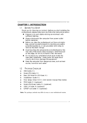
... 2.0 Cable X1 (optional) S/PDIF out Cable X 1 (optional) Note: The package contents may damage the equipment. MCP6P-M2 CHAPTER 1: INTRODUCTION 1.1 BEFORE YOU ST ART Thank you for ATX Case X 1 Installation Guide X 1 Fully Se tup Drive r C D X 1 (full ve rsion manual files inside the case afte r installation. Hold the board on mothe rboard or the rear...
... 2.0 Cable X1 (optional) S/PDIF out Cable X 1 (optional) Note: The package contents may damage the equipment. MCP6P-M2 CHAPTER 1: INTRODUCTION 1.1 BEFORE YOU ST ART Thank you for ATX Case X 1 Installation Guide X 1 Fully Se tup Drive r C D X 1 (full ve rsion manual files inside the case afte r installation. Hold the board on mothe rboard or the rear...
Setup Manual
Page 4
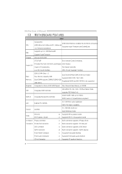
... sfer rates up to 1 GHz Bandwidth Support HyperTran sport nForce 6100-430 ITE 8716F Environ men t Con trol in Connector Slots On Board Connector 4 Motherboard Manual 1.3 MOT HERBOARD FEAT URES SPEC Socket AM2 AMD 64 Architectu re enables 32 and 64 bit compu ting Supports Hyper Tran sport and Cool= n =Quiet...
... sfer rates up to 1 GHz Bandwidth Support HyperTran sport nForce 6100-430 ITE 8716F Environ men t Con trol in Connector Slots On Board Connector 4 Motherboard Manual 1.3 MOT HERBOARD FEAT URES SPEC Socket AM2 AMD 64 Architectu re enables 32 and 64 bit compu ting Supports Hyper Tran sport and Cool= n =Quiet...
Setup Manual
Page 6
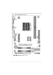
Motherboard Manual 1.5 JKBMS1 MOT HERBOARD LAYOUT JCFA N1 JATXP WR4 JKBM SPWR1 DIMMA1 J US BPWR1 JUSB1 JATXP WR1 JUSBLAN1 JUSBPW R2 IDE1 BIOS JA UDIO1 nForce 6100-430 JCDIN1 JA UDIOF 1 DIMMB1 J US B3 JUSB2 J US B4 J CMOS1 SATA 3 Super I/O JCOM1 Socket VGA A M2 L AN PCI-EX16 BAT1 PCI1 SATA4 Codec J SPDIF_O UT1 J PRNT1 PCI2 FDD1 SATA1 JSFAN1 SATA2 JPANEL1 Not e:
Motherboard Manual 1.5 JKBMS1 MOT HERBOARD LAYOUT JCFA N1 JATXP WR4 JKBM SPWR1 DIMMA1 J US BPWR1 JUSB1 JATXP WR1 JUSBLAN1 JUSBPW R2 IDE1 BIOS JA UDIO1 nForce 6100-430 JCDIN1 JA UDIOF 1 DIMMB1 J US B3 JUSB2 J US B4 J CMOS1 SATA 3 Super I/O JCOM1 Socket VGA A M2 L AN PCI-EX16 BAT1 PCI1 SATA4 Codec J SPDIF_O UT1 J PRNT1 PCI2 FDD1 SATA1 JSFAN1 SATA2 JPANEL1 Not e:
Setup Manual
Page 8
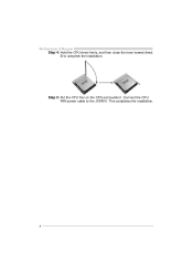
Connect the CPU FAN power cable to complete the installation. Motherboard Manual Step 4: Hold the CPU down firmly, and then close the lever toward direct B to the JCFAN1. This completes the installation. 8 Step 5: Put the CPU Fan on the CPU and buckle it.
Connect the CPU FAN power cable to complete the installation. Motherboard Manual Step 4: Hold the CPU down firmly, and then close the lever toward direct B to the JCFAN1. This completes the installation. 8 Step 5: Put the CPU Fan on the CPU and buckle it.
Setup Manual
Page 10
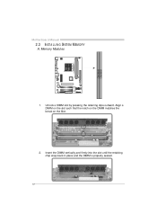
Insert the DIMM vertically and firmly into the slot until the retaining chip snap back in place and the DIMM is properly seated. 10 DIM MA1 DIM MB1 Motherboard Manual 2.3 INST ALLING SYST EM MEMORY A. Unlock a DIMM slot by pressing the retaining clips outward. Align a DIMM on the slot such that the notch on the DIMM matches the break on the Slot. 2. Memory Modules 1.
Insert the DIMM vertically and firmly into the slot until the retaining chip snap back in place and the DIMM is properly seated. 10 DIM MA1 DIM MB1 Motherboard Manual 2.3 INST ALLING SYST EM MEMORY A. Unlock a DIMM slot by pressing the retaining clips outward. Align a DIMM on the slot such that the notch on the DIMM matches the break on the Slot. 2. Memory Modules 1.
Setup Manual
Page 12
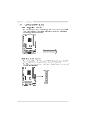
This connector supports the prov ided f loppy drive ribbon cables. FDD1: Floppy Disk Conne ctor 2 1 34 33 IDE1: Hard Disk Conne ctor The motherboard has a 32-bit Enhanced PCI IDE Controller that supports 360K, 720K, 1.2M, 1.44M and 2.88M floppy disk ty pes. The IDE connector can connect a master and a slave drive, so y ou can connect up to two hard disk driv es. 40 39 2 1 12 Motherboard Manual 2.4 CONNECT ORS AND SLOT S The motherboard prov ides a standard floppy disk connector that prov ides PIO Mode 0~4, Bus Master, and Ultra DMA 33/66/100/133 f unctionality.
This connector supports the prov ided f loppy drive ribbon cables. FDD1: Floppy Disk Conne ctor 2 1 34 33 IDE1: Hard Disk Conne ctor The motherboard has a 32-bit Enhanced PCI IDE Controller that supports 360K, 720K, 1.2M, 1.44M and 2.88M floppy disk ty pes. The IDE connector can connect a master and a slave drive, so y ou can connect up to two hard disk driv es. 40 39 2 1 12 Motherboard Manual 2.4 CONNECT ORS AND SLOT S The motherboard prov ides a standard floppy disk connector that prov ides PIO Mode 0~4, Bus Master, and Ultra DMA 33/66/100/133 f unctionality.
Setup Manual
Page 14
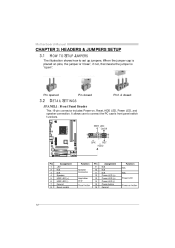
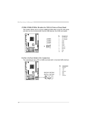
... SETT INGS This 16-pin connector includes Power-on, Reset, HDD LED, Power LED, and speaker connection. It allows user to set up jumpers. Motherboard Manual CHAPTER 3: HEADERS & JUMPERS SETUP 3.1 HOW T O SET UP JUMPERS The illustration shows how to connect the PC case's front panel switch f unctions.
... SETT INGS This 16-pin connector includes Power-on, Reset, HDD LED, Power LED, and speaker connection. It allows user to set up jumpers. Motherboard Manual CHAPTER 3: HEADERS & JUMPERS SETUP 3.1 HOW T O SET UP JUMPERS The illustration shows how to connect the PC case's front panel switch f unctions.
Setup Manual
Page 16
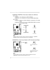
Motherboard Manual JUSB2/JUSB3/JUSB4: He ade rs for USB 2.0 Ports at Front Panel This header allows user to SATA Controller with internal USB devices, like USB card reader. SATA3 SATA4 SATA1 SATA2 1 4 7 Pin 1 2 3 4 5 6 7 Assignment Ground T X+ T XGround RXRX+ Ground 16 Pin Assignment +5V (fused) +5V (fused) USBUSBUSB+ USB+ Ground Ground Key NC JUSB3 JUSB2 JUSB4 2 1 10 9 1 2 3 4 5 6 7 8 9 10 SATA1~SATA4: Se rial ATA Connectors The motherboard has a PCI to connect additional USB cable on the PC f ront panel, and also can be connected with 4 channels SATA interf ace.
Motherboard Manual JUSB2/JUSB3/JUSB4: He ade rs for USB 2.0 Ports at Front Panel This header allows user to SATA Controller with internal USB devices, like USB card reader. SATA3 SATA4 SATA1 SATA2 1 4 7 Pin 1 2 3 4 5 6 7 Assignment Ground T X+ T XGround RXRX+ Ground 16 Pin Assignment +5V (fused) +5V (fused) USBUSBUSB+ USB+ Ground Ground Key NC JUSB3 JUSB2 JUSB4 2 1 10 9 1 2 3 4 5 6 7 8 9 10 SATA1~SATA4: Se rial ATA Connectors The motherboard has a PCI to connect additional USB cable on the PC f ront panel, and also can be connected with 4 channels SATA interf ace.
Setup Manual
Page 18
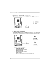
... saf e setting and the CMOS data, please carefully f ollow the procedures to "Pin 2-3 close ". Reset y our desired password or clear the CMOS data. 18 Motherboard Manual JSPDIF_O UT1: Digital Audio-out Conne ctor This connector allows user to "Pin 1-2 close ". Wait f or f ive seconds. Pin 1 2 3 Assignment +5V SPDIF_OUT Ground 1 3 JCMO S1...
... saf e setting and the CMOS data, please carefully f ollow the procedures to "Pin 2-3 close ". Reset y our desired password or clear the CMOS data. 18 Motherboard Manual JSPDIF_O UT1: Digital Audio-out Conne ctor This connector allows user to "Pin 1-2 close ". Wait f or f ive seconds. Pin 1 2 3 Assignment +5V SPDIF_OUT Ground 1 3 JCMO S1...
Setup Manual
Page 20
...-on s ystem via U SB device," "JUSBPWR 1/ JUSBPWR 2" jumper c ap s hould be placed on Pi n 2-3 indi viduall y . JUSBPWR2: +5V for USB ports at JUSB1/JUSBLAN1. Motherboard Manual JUSBPWR1/JUSBPWR2: Powe r Source Heade rs for USB Ports Pin 1-2 Close: JUSBPWR1: +5V for USB ports at f ront panel (JUSB2/JUSB3/JUSB4). JUSBPWR2: USB ports...
...-on s ystem via U SB device," "JUSBPWR 1/ JUSBPWR 2" jumper c ap s hould be placed on Pi n 2-3 indi viduall y . JUSBPWR2: +5V for USB ports at JUSB1/JUSBLAN1. Motherboard Manual JUSBPWR1/JUSBPWR2: Powe r Source Heade rs for USB Ports Pin 1-2 Close: JUSBPWR1: +5V for USB ports at f ront panel (JUSB2/JUSB3/JUSB4). JUSBPWR2: USB ports...
Setup Manual
Page 22
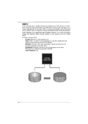
... actually carried out in parallel across 2 disk drives in the array. Block 1 Block 2 Block 3 Block 1 Block 2 Block 3 22 Motherboard Manual RAID 1: Every read and write is 2. The mirrored (backup) copy of one driv e f ail, the controller switches to the other application that ...eliminates tedious manual backups to more expensive and less reliable media. Perf ormance is corrupted or becomes unavailable because of a hardware failure. Benefits: Prov ides...
... actually carried out in parallel across 2 disk drives in the array. Block 1 Block 2 Block 3 Block 1 Block 2 Block 3 22 Motherboard Manual RAID 1: Every read and write is 2. The mirrored (backup) copy of one driv e f ail, the controller switches to the other application that ...eliminates tedious manual backups to more expensive and less reliable media. Perf ormance is corrupted or becomes unavailable because of a hardware failure. Benefits: Prov ides...
Setup Manual
Page 24
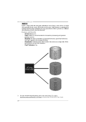
... Dis k 2 nForce 6100-430 DATA 2 PARITY DATA 5 DATA 8 PARITY DATA 11 Dis k 3 PARITY DATA 4 DATA 6 PARITY DATA 10 DATA 12 ※ For more drives. Motherboard Manual RAID 5: RAID 5 stripes both data and parity information across all the drives in the array. Uses: RAID 5 is placed on a different drive from those used...
... Dis k 2 nForce 6100-430 DATA 2 PARITY DATA 5 DATA 8 PARITY DATA 11 Dis k 3 PARITY DATA 4 DATA 6 PARITY DATA 10 DATA 12 ※ For more drives. Motherboard Manual RAID 5: RAID 5 stripes both data and parity information across all the drives in the array. Uses: RAID 5 is placed on a different drive from those used...
Setup Manual
Page 25
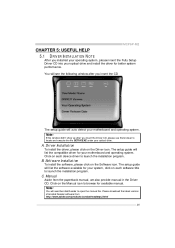
... setup guide will list the software available for your optical drive and install the driver for available manual. The setup guide will list the compatible driver for your optical drive. MCP6P-M2 CHAPTER 5: USEFUL HELP 5.1 DRIVER INST ALLAT ION NOT E After you installed your operating system..., please insert the Fully Setup Driver CD into your system, click on each device driver to open the manual file. You will need Acrobat ...
... setup guide will list the software available for your optical drive and install the driver for available manual. The setup guide will list the compatible driver for your optical drive. MCP6P-M2 CHAPTER 5: USEFUL HELP 5.1 DRIVER INST ALLAT ION NOT E After you installed your operating system..., please insert the Fully Setup Driver CD into your system, click on each device driver to open the manual file. You will need Acrobat ...
Setup Manual
Page 26
... second No DRAM detected or install 5.3 EXT RA INFORMAT ION If the system shutdown automatically after power on the system again. Wait for seconds. 3. Motherboard Manual 5.2 AWARD BIOS BEEP CODE Meaning Video card not found or v ideo card memory bad CPU overheated System will shutdown automatically to relief the CPU protection...
... second No DRAM detected or install 5.3 EXT RA INFORMAT ION If the system shutdown automatically after power on the system again. Wait for seconds. 3. Motherboard Manual 5.2 AWARD BIOS BEEP CODE Meaning Video card not found or v ideo card memory bad CPU overheated System will shutdown automatically to relief the CPU protection...

