Setup Manual
Page 4
... x 2 Fan Speed Controller ITE's "Smart Guardian" function Dual Channel Mode DDR2 memory modu le Supports DDR2 533 / 667 / 800 Registered DIMM and E CC DIMM is not supported Max Shared Video Memory is 512MB Ultra DMA 33 / 66 / 100 / 133 Bu s Master Mode supports PIO Mode 0 ~4, Data tran ... SATA devices Supports fron t panel facilities Supports fron t panel audio fun ction Supports CD audio-in function Main Memory Max Memory Capacity 4G B Each DIMM supports 256 MB/512 MB/1GB/ 2GB DDR2 Graphics IDE Integrated in n Force 6100-430 Chipset Integrated IDE Con troller SATA II Integrated Serial ATA...
... x 2 Fan Speed Controller ITE's "Smart Guardian" function Dual Channel Mode DDR2 memory modu le Supports DDR2 533 / 667 / 800 Registered DIMM and E CC DIMM is not supported Max Shared Video Memory is 512MB Ultra DMA 33 / 66 / 100 / 133 Bu s Master Mode supports PIO Mode 0 ~4, Data tran ... SATA devices Supports fron t panel facilities Supports fron t panel audio fun ction Supports CD audio-in function Main Memory Max Memory Capacity 4G B Each DIMM supports 256 MB/512 MB/1GB/ 2GB DDR2 Graphics IDE Integrated in n Force 6100-430 Chipset Integrated IDE Con troller SATA II Integrated Serial ATA...
Setup Manual
Page 10
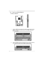
Align a DIMM on the slot such that the notch on the DIMM matches the break on the Slot. 2. Insert the DIMM vertically and firmly into the slot until the retaining chip snap back in place and the DIMM is properly seated. 10 DIM MA1 DIM MB1 Unlock a DIMM slot by pressing the retaining clips outward. Memory Modules 1. Motherboard Manual 2.3 INST ALLING SYST EM MEMORY A.
Align a DIMM on the slot such that the notch on the DIMM matches the break on the Slot. 2. Insert the DIMM vertically and firmly into the slot until the retaining chip snap back in place and the DIMM is properly seated. 10 DIM MA1 DIM MB1 Unlock a DIMM slot by pressing the retaining clips outward. Memory Modules 1. Motherboard Manual 2.3 INST ALLING SYST EM MEMORY A.
Setup Manual
Page 11
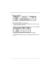
Dual Channel Memory installation To trigger the Dual Channel f unction of the same density in pair, shown in the f ollowing table. C. Memory Capacity DIMM Socket Location DIMMA1 DIMMB1 DDR2 Module 256MB/512MB/1GB/2GB 256MB/512MB/1GB/2GB Total Memory Size Max is 4GB. Dual Channel Status Disabled Disabled Enabled DIMMA1 O X O DIMMB1 X O O (O means memory installed, X means memory not installed.) The DRAM bus width of the memory module must meet the following requirements: Install memory module of the motherboard, the memory module must be the same (x8 or x16) 11 MCP6P-M2 B.
Dual Channel Memory installation To trigger the Dual Channel f unction of the same density in pair, shown in the f ollowing table. C. Memory Capacity DIMM Socket Location DIMMA1 DIMMB1 DDR2 Module 256MB/512MB/1GB/2GB 256MB/512MB/1GB/2GB Total Memory Size Max is 4GB. Dual Channel Status Disabled Disabled Enabled DIMMA1 O X O DIMMB1 X O O (O means memory installed, X means memory not installed.) The DRAM bus width of the memory module must meet the following requirements: Install memory module of the motherboard, the memory module must be the same (x8 or x16) 11 MCP6P-M2 B.
Setup Manual
Page 27
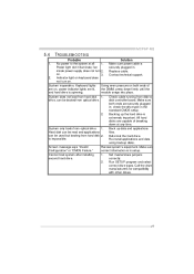
... cable running from hard disk 1. Keyboard lights Using even pressure on both ends are capable of are lit, the DIMM, press down at all securely plugged in ; Ref ormat the hard driv e. MCP6P-M2 5.4 1. Power light don't illuminate, f an inside power supply does not turn on , power indicator lights are on . Contact technical...
... cable running from hard disk 1. Keyboard lights Using even pressure on both ends are capable of are lit, the DIMM, press down at all securely plugged in ; Ref ormat the hard driv e. MCP6P-M2 5.4 1. Power light don't illuminate, f an inside power supply does not turn on , power indicator lights are on . Contact technical...
