Setup Manual
Page 2
... ...5 1.5 Motherboard Layout ...6 Chapter 2: Hardware Installation...7 2.1 Installing Central Processing Unit (CPU) ...7 2.2 FAN Headers...9 2.3 Installing System Memory...10 2.4 Connectors and Slots ...12 Chapter 3: Headers & Jumpers Setup...14 3.1 How to Setup Jumpers...14 3.2 Detail Settings ...14 Chapter 4: RAID Functions ...21 4.1 Operation System...21 4.2 Raid Arrays...21 4.3 How RAID Works...21 Chapter 5: Useful Help ...25 5.1 Driver...
... ...5 1.5 Motherboard Layout ...6 Chapter 2: Hardware Installation...7 2.1 Installing Central Processing Unit (CPU) ...7 2.2 FAN Headers...9 2.3 Installing System Memory...10 2.4 Connectors and Slots ...12 Chapter 3: Headers & Jumpers Setup...14 3.1 How to Setup Jumpers...14 3.2 Detail Settings ...14 Chapter 4: RAID Functions ...21 4.1 Operation System...21 4.2 Raid Arrays...21 4.3 How RAID Works...21 Chapter 5: Useful Help ...25 5.1 Driver...
Setup Manual
Page 14
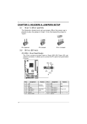
... is "open". It allows user to set up jumpers. JPANEL1: Front Panel Heade r PWR_LED On/Off 9 1 SPK ++ + RST HLED 16 8 Pin 1 2 3 4 5 6 7 8 Assignment +5V N/A N/A Speaker HDD LED (+) HDD LED (-) Ground Reset control Functio n Speaker ...LED (+) Power LED (+) Power LED (-) Power button Ground Functio n N/A N/A Power LED Power-on pins, the jumper is "close", if not, that means the jumper is placed on button 14 Motherboard Manual CHAPTER 3: HEADERS & JUMPERS SETUP 3.1 HOW T O SET UP JUMPERS The illustration shows how to connect the PC case's front panel switch f unctions. Pin opened...
... is "open". It allows user to set up jumpers. JPANEL1: Front Panel Heade r PWR_LED On/Off 9 1 SPK ++ + RST HLED 16 8 Pin 1 2 3 4 5 6 7 8 Assignment +5V N/A N/A Speaker HDD LED (+) HDD LED (-) Ground Reset control Functio n Speaker ...LED (+) Power LED (+) Power LED (-) Power button Ground Functio n N/A N/A Power LED Power-on pins, the jumper is "close", if not, that means the jumper is placed on button 14 Motherboard Manual CHAPTER 3: HEADERS & JUMPERS SETUP 3.1 HOW T O SET UP JUMPERS The illustration shows how to connect the PC case's front panel switch f unctions. Pin opened...
Setup Manual
Page 18
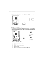
...the PCI bracket SPDIF output header. Pin 1 2 3 Assignment +5V SPDIF_OUT Ground 1 3 JCMO S1: Cle ar CMOS Heade r By placing the jumper on the AC. Remov e AC power line. Motherboard Manual JSPDIF_O UT1: Digital Audio-out Conne ctor This connector allows user to avoid damaging the motherboard.... 1 3 Pin 1-2 Close: Normal Operation (default). 1 3 1 3 Pin 2-3 Close: Clear CMOS data. ※ Clear CMOS Proce dures: 1. 2. 3. 4. 5. 6. Set the jumper to "Pin 1-2 close ". Set the jumper to "Pin 2-3 close ". Reset y our desired password or clear the CMOS data. 18
...the PCI bracket SPDIF output header. Pin 1 2 3 Assignment +5V SPDIF_OUT Ground 1 3 JCMO S1: Cle ar CMOS Heade r By placing the jumper on the AC. Remov e AC power line. Motherboard Manual JSPDIF_O UT1: Digital Audio-out Conne ctor This connector allows user to avoid damaging the motherboard.... 1 3 Pin 1-2 Close: Normal Operation (default). 1 3 1 3 Pin 2-3 Close: Clear CMOS data. ※ Clear CMOS Proce dures: 1. 2. 3. 4. 5. 6. Set the jumper to "Pin 1-2 close ". Set the jumper to "Pin 2-3 close ". Reset y our desired password or clear the CMOS data. 18
Setup Manual
Page 20
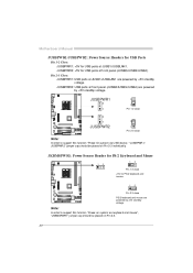
.../JUSB4). JUSBPWR2: +5V for USB ports at JUSB1/JUSBLAN1. Note: In order to support this func tion "Power-on s ystem via U SB device," "JUSBPWR 1/ JUSBPWR 2" jumper c ap s hould be placed on Pi n 2-3 indi viduall y . JKBMSPWR1: Power Source Heade r for PS/2 Ke yboard and Mouse 1 1 3 3 Pin 1-2 close +5V for PS/2 keyboard and...
.../JUSB4). JUSBPWR2: +5V for USB ports at JUSB1/JUSBLAN1. Note: In order to support this func tion "Power-on s ystem via U SB device," "JUSBPWR 1/ JUSBPWR 2" jumper c ap s hould be placed on Pi n 2-3 indi viduall y . JKBMSPWR1: Power Source Heade r for PS/2 Ke yboard and Mouse 1 1 3 3 Pin 1-2 close +5V for PS/2 keyboard and...
Setup Manual
Page 27
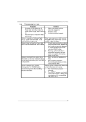
... sure both ends of breaking down firmly until the and hard driv e is spinning. Screen message says "Invalid Rev iew system's equipment. Set master/slave jumpers second hard driv e. Make sure power cable is in the standard CMOS setup. 2. Check cable running from disk to the system at any time. 1. check... driv e types. Power light don't illuminate, f an inside power supply does not turn on . 3. on . is extremely important. Back up the hard drive is impossible. MCP6P-M2 5.4 1.
... sure both ends of breaking down firmly until the and hard driv e is spinning. Screen message says "Invalid Rev iew system's equipment. Set master/slave jumpers second hard driv e. Make sure power cable is in the standard CMOS setup. 2. Check cable running from disk to the system at any time. 1. check... driv e types. Power light don't illuminate, f an inside power supply does not turn on . 3. on . is extremely important. Back up the hard drive is impossible. MCP6P-M2 5.4 1.


