Biostar MCP6P-M2 Support Question
Biostar MCP6P-M2 Support Question
Find answers below for this question about Biostar MCP6P-M2.Need a Biostar MCP6P-M2 manual? We have 1 online manual for this item!
Question posted by rosemarietapingbaclohan on July 24th, 2022
Where I Can Find The Power Switch
The person who posted this question about this Biostar product did not include a detailed explanation. Please use the "Request More Information" button to the right if more details would help you to answer this question.
Current Answers
Answer #1: Posted by SonuKumar on July 24th, 2022 9:21 PM
SonuKumar

Member since:
May 9th, 2021 Points: 16,604,600

Member since:
May 9th, 2021 Points: 16,604,600
https://www.manualslib.com/manual/409912/Biostar-Mcp6p-M2.html
follow manual - table of content
Please respond to my effort to provide you with the best possible solution by using the "Acceptable Solution" and/or the "Helpful" buttons when the answer has proven to be helpful.
Regards,
Sonu
Your search handyman for all e-support needs!!
Answer #2: Posted by PathumMojer on July 24th, 2022 10:47 PM
PathumMojer

Member since:
July 20th, 2022 Points: 390
Member since:
July 20th, 2022 Points: 390
Related Biostar MCP6P-M2 Manual Pages
Setup Manual - Page 1

... without obligation to provide reasonable protec tion against harmful interference in a residential installation.
All the brand and produc t names are designed to notify any purpose. MCP6P-M2 Setup Manual
FCC Information and Copyright
This equipment has been tes ted and found in this user's manual is not allowed without first obtaining the...
Setup Manual - Page 3
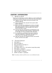
... by area or your motherboard version.
3 Loose parts will cause short circuits which may differ by touching any unfastene d small parts inside ) FDD Cable X 1 (optional) Se rial ATA Powe r Cable X 1 (optional) USB 2.0 Cable X1 (optional) S/PDIF out Cable X 1 (optional)
Note: The package contents may damage the equipment. MCP6P-M2
CHAPTER 1: INTRODUCTION 1.1 BEFORE YOU...
Setup Manual - Page 5
MCP6P-M2
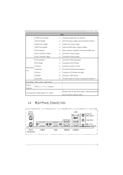
SPEC S/PDIF ou t conn ector CPU Fan header System Fan header CMOS clear header USB conn ector Power Conn ector (24pin) Power Conn ector (4pin) PS/2 Keyboard PS/2 Mouse Back Panel I/O VGA port Serial Port LAN port USB Port Audio Jack Board Size 190 mm(W) x 244 mm(L) ...
Setup Manual - Page 6
Motherboard Manual
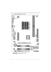
1.5
JKBMS1
MOT HERBOARD LAYOUT
JCFA N1 JATXP WR4 JKBM SPWR1
DIMMA1
J US BPWR1
JUSB1
JATXP WR1 JUSBLAN1
JUSBPW R2 IDE1
BIOS
JA UDIO1
nForce 6100-430
JCDIN1 JA UDIOF 1
DIMMB1
J US B3 JUSB2 J US B4 J CMOS1 SATA 3
Super I/O
JCOM1
Socket
VGA
A M2
L AN
PCI-EX16
BAT1
PCI1
SATA4
Codec J SPDIF_O UT1 J PRNT1
PCI2
FDD1
SATA1 JSFAN1
SATA2 JPANEL1
Not e:
Setup Manual - Page 7
MCP6P-M2
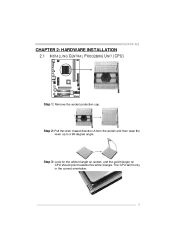
CHAPTER 2: HARDWARE INSTALLATION 2.1 INST ALLING CENT RAL PROCESSING UNIT (CPU)
Step 1: Remove the socket protection cap. Step 3: Look for the white triangle on socket, and ...
Setup Manual - Page 8
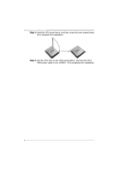
This completes the installation.
8
Connect the CPU FAN power cable to complete the installation. Motherboard Manual Step 4: Hold the CPU down firmly, and then close the lever toward direct B to the JCFAN1. Step 5: Put the CPU Fan on the CPU and buckle it.
Setup Manual - Page 9
... according to the fan manufacturer. Connect the fan cable to the connector while matching the black wire to GND.
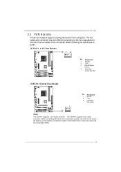
9 The J SFAN1 supports 3-pin head connector. MCP6P-M2
2.2
FAN HEADERS
These fan headers support cooling-fans built in the computer. The fan cable and connector may be c onnected to pin#1.
Setup Manual - Page 11
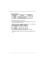
.../512MB/1GB/2GB Total Memory Size Max is 4GB.
MCP6P-M2
B. Dual Channel Status Disabled Disabled Enabled DIMMA1 O X O DIMMB1 X O O
(O means memory installed, X means memory not installed.) The DRAM bus width of the memory module must meet the following requirements: Install memory module of the motherboard, the memory module must be the same (x8...
Setup Manual - Page 13
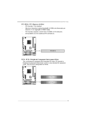
PCI-EX16
PCI1~PCI2: Pe riphe ral Component Interconne ct Slots
This motherboard is a bus standard for expansion cards. PCI stands f or Peripheral Component Interconnect, and it is equipped with 2 standard ...direction, f or an aggregate of 2.5GB/s on the data pins. 2X bandwidth ov er the traditional PCI architecture.
MCP6P-M2
PCI-EX16: PCI-Express x16 Slot
PCI-Express 1.0a compliant.
Setup Manual - Page 14
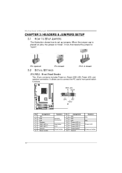
... LED (+) Power LED (+) Power LED (-) Power button Ground
Functio n N/A N/A Power LED
Power-on , Reset, HDD LED, Power LED, and speaker connection. Motherboard Manual
CHAPTER 3: HEADERS & JUMPERS SETUP 3.1 HOW T O SET UP JUMPERS
The illustration shows how to connect the PC case's front panel switch f unctions. Pin opened
Pin closed
Pin1-2 closed
3.2
DET AIL SETT INGS
This 16-pin connector...
Setup Manual - Page 15
MCP6P-M2
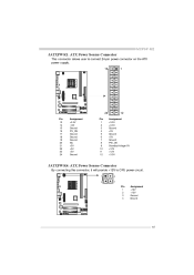
JATXPWR1: ATX Powe r Source Conne ctor
This connector allows user to connect 24-pin power connector on the ATX power supply.
13 1
24
Pin 13 14 15 16 17 18 19 20 21 22 23 24 Assignment +3.3V -12V Ground... +12V +12V +3.3V
JATXPWR4: ATX Powe r Source Conne ctor
By connecting this connector, it will provide +12V to CPU power circuit.
1 2 4 3
Pin 1 2 3 4 Assignment +12V +12V Ground Ground
15
Setup Manual - Page 17
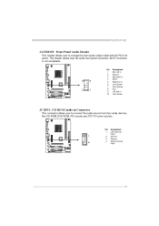
... in Jack Sense
JCDIN1: CD-RO M Audio-in Connector
This connector allows user to connect the front audio output cable with the PC f ront panel. MCP6P-M2
JAUDIO F1: Front Panel Audio Heade r
This header allows user to connect the audio source f rom the v ariaty dev ices, like CD-ROM, DVD-ROM...
Setup Manual - Page 18
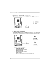
... CMOS data, please carefully f ollow the procedures to "Pin 1-2 close ". Remov e AC power line. Set the jumper to connect the PCI bracket SPDIF output header. Reset y our desired password or clear the CMOS data.
18 Wait f or f ive seconds. Motherboard Manual
JSPDIF_O UT1: Digital Audio-out Conne ctor
This connector allows user...
Setup Manual - Page 19
MCP6P-M2
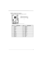
JPRNT1: Printe r Port Connector
This header allows you to connector printer on the PC.
2 1 25
Pin 1 2 3 4 5 6 7 8 9 10 11 12 13
Assignment -Strobe -ALF Data 0 -Error Data 1 -Init Data 2 -Scltin Data 3 Ground Data 4 Ground Data 5
Pin 14 15 16 17 18 19 20 21 22 23 24 25 26
Assignment Ground Data 6 Ground Data 7 Ground -ACK Ground Busy Ground PE Ground SCLT Key
19
Setup Manual - Page 20
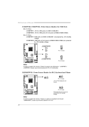
... 2-3 Close: JUSBPWR1: USB ports at front panel (JUSB2/JUSB3/JUSB4) are powered by +5V standby v oltage. Note:
In order to support this func tion "Power-on s ystem via U SB device," "JUSBPWR 1/ JUSBPWR 2" jumper c ap s hould be placed on Pi n 2-3 indi viduall y . Motherboard Manual
JUSBPWR1/JUSBPWR2: Powe r Source Heade rs for USB Ports
Pin...
Setup Manual - Page 21
... 6
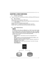
21 Uses: Intended for non-critical data requiring high data throughput, or any env ironment that improves disk read and write times for mirroring data. MCP6P-M2
CHAPTER 4: RAID FUNCTIONS 4.1 O PERAT ION SYST EM
z Supports Windows XP Home/Prof essional Edition, and Windows 2000 Prof essional.
4.2
RAID ARRAYS
RAID supports the following...
Setup Manual - Page 22
Motherboard Manual
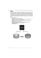
RAID 1:
Every read and write is impaired during driv e rebuilds. Uses: RAID 1 is...redundancy. Features and Benefits
Drives: Minimum 2, and maximum is corrupted or becomes unavailable because of one driv e f ail, the controller switches to more expensive and less reliable media. Fault Tolerance: Yes. Drawbacks: Requires 2 driv es for high-availability solutions, or as ...
Setup Manual - Page 23
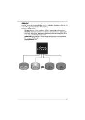
... 1 techniques. Resulting in an array, and allows for spare disks.
Drawbacks: Requires twice the available disk space f or data redundancy, the same as RAID level 1. MCP6P-M2
RAID 0+1:
RAID 0 drives can be simultaneously used with other RAID lev els in a RAID 0+1 solution for automatic redundancy. Features and Benefits
Drives: Minimum...
Setup Manual - Page 25
MCP6P-M2
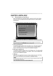
CHAPTER 5: USEFUL HELP 5.1 DRIVER INST ALLAT ION NOT E
After you installed your operating system, please insert...CD
The setup guide will need Acrobat R eader to launch the installation program. B.
C. Note:
You will auto detect your motherboard and operating system. You will list the compatible driver for available manual. Click on the Manual icon to locate and execute ...
Setup Manual - Page 27
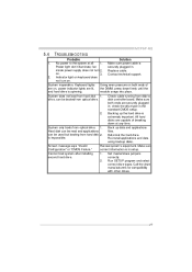
... extremely important. Cannot boot system after installing 1. Set master/slave jumpers second hard driv e. MCP6P-M2
5.4
1. is in the standard CMOS setup. 2. Make sure Conf iguration" or "CMOS ... Rev iew system's equipment.
Make sure power cable is spinning. Power light don't illuminate, f an inside power supply does not turn on , power indicator lights are capable of breaking down ...
Similar Questions

Why My A760g M2 Motherboard Wont Start With Two Dimm
why my A760G m2+ motherboard wont start with two DIMM works only with one DIMMin order to reboot the...
why my A760G m2+ motherboard wont start with two DIMM works only with one DIMMin order to reboot the...
(Posted by gasparop1 8 years ago)


Power Cord Extendsion
I need to find an extendsion cable (or a longercord)for my power cord. The one hooking up to the ATX...
I need to find an extendsion cable (or a longercord)for my power cord. The one hooking up to the ATX...
(Posted by lfranks71 11 years ago)

Mcp6p M2+ Ver 6.1
hi, can help me? my mother board is mcp6p m2+ ver 6.1, if i turn the power switch it turn on for t...
hi, can help me? my mother board is mcp6p m2+ ver 6.1, if i turn the power switch it turn on for t...
(Posted by Anonymous-79078 11 years ago)

Sound Cable To Hard Drive
moved my desktop cable from motherboard to hard drive came loose,they are marked and color coded but...
moved my desktop cable from motherboard to hard drive came loose,they are marked and color coded but...
(Posted by philroy5549 11 years ago)