Motherboard DIY Troubleshooting Guide
Page 1
Motherboard P4V8X-MX User Guide
Motherboard P4V8X-MX User Guide
Motherboard DIY Troubleshooting Guide
Page 3
Contents Notices ...v Safety Information vi About This Guide vii P4V8X-MX Specifications Summary viii Chapter 1: Product Introduction 1.1 Welcome 1-2 1.2 Package Contents 1-2 1.3 Special Features 1-2 1.3.1 Product highlights 1-2 1.3.2 Innovative ASUS features 11.4 Before You Proceed 1-4 1.5 Motherboard Overview 1-5 1.5.1 Motherboard layout 1-5 1.5.2 Placement direction 1-6 1.5.3 Screw holes 1-6 1.6 Central Processing Unit (CPU 1-7 1.6.1 Overview 1-7 1.6.2 Installing the CPU 1-8 1.7 System Memory 1-9 1.7.1 Overview 1-9 1.7.2 Memory configurations...
Contents Notices ...v Safety Information vi About This Guide vii P4V8X-MX Specifications Summary viii Chapter 1: Product Introduction 1.1 Welcome 1-2 1.2 Package Contents 1-2 1.3 Special Features 1-2 1.3.1 Product highlights 1-2 1.3.2 Innovative ASUS features 11.4 Before You Proceed 1-4 1.5 Motherboard Overview 1-5 1.5.1 Motherboard layout 1-5 1.5.2 Placement direction 1-6 1.5.3 Screw holes 1-6 1.6 Central Processing Unit (CPU 1-7 1.6.1 Overview 1-7 1.6.2 Installing the CPU 1-8 1.7 System Memory 1-9 1.7.1 Overview 1-9 1.7.2 Memory configurations...
Motherboard DIY Troubleshooting Guide
Page 6
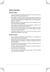
... you are not sure about the voltage of the electrical outlet you add a device. • Before connecting or removing signal cables from the motherboard, ensure that your power supply is broken, do not try to fix it , carefully read all the manuals that the power cables for the...to or from the system, ensure that came with the product, contact a qualified service technician or your retailer. Operation safety • Before installing the motherboard and adding devices on a stable surface. • If you detect any damage, contact your local power company. • If the power supply is...
... you are not sure about the voltage of the electrical outlet you add a device. • Before connecting or removing signal cables from the motherboard, ensure that your power supply is broken, do not try to fix it , carefully read all the manuals that the power cables for the...to or from the system, ensure that came with the product, contact a qualified service technician or your retailer. Operation safety • Before installing the motherboard and adding devices on a stable surface. • If you detect any damage, contact your local power company. • If the power supply is...
Motherboard DIY Troubleshooting Guide
Page 7
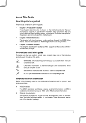
... the following sources for additional information and for product and software updates. 1. ASUS websites The ASUS websites worldwide provide updated information on the motherboard. • Chapter 2: BIOS Information This chapter tells how to the ASUS contact information. 2. It includes description of the motherboard and the new technology it supports. WARNING: Information to prevent injury to...
... the following sources for additional information and for product and software updates. 1. ASUS websites The ASUS websites worldwide provide updated information on the motherboard. • Chapter 2: BIOS Information This chapter tells how to the ASUS contact information. 2. It includes description of the motherboard and the new technology it supports. WARNING: Information to prevent injury to...
Motherboard DIY Troubleshooting Guide
Page 10
This chapter describes the motherboard features and the new technologies it supports. 1Product Introduction
This chapter describes the motherboard features and the new technologies it supports. 1Product Introduction

Motherboard DIY Troubleshooting Guide
Page 11
... the items in the long line of advanced features. See page 1-14 for the following items. Motherboard ASUS P4V8X-MX motherboard Cables 1 x UltraDMA 133/100/66 cable 1 x Serial ATA / Power cable 1 x Floppy Disk Drive cable Accessories I/O shield Application CDs ASUS motherboard support CD Documentation User guide If any of the above items is the mainstream VGA interface...
... the items in the long line of advanced features. See page 1-14 for the following items. Motherboard ASUS P4V8X-MX motherboard Cables 1 x UltraDMA 133/100/66 cable 1 x Serial ATA / Power cable 1 x Floppy Disk Drive cable Accessories I/O shield Application CDs ASUS motherboard support CD Documentation User guide If any of the above items is the mainstream VGA interface...

Motherboard DIY Troubleshooting Guide
Page 12
...protection feature without the need to open the case to overclocking failure, there is embedded in a support CD. ASUS motherboards now enable users to enjoy this motherboard to pay for next generation components and peripherals. No more colorful and vivid image on your screen... (See page 2-5). ASUS EZ Flash BIOS With ASUS EZ Flash, you a fast and reliable connection to 40 times faster at 480 MB/s, for easy connectivity and ultra-fast data transfer rate (See pages 1-17 & 1-20 for details). Users can update BIOS before entering operating system. ASUS P4V8X-MX Motherboard 1-3
...protection feature without the need to open the case to overclocking failure, there is embedded in a support CD. ASUS motherboards now enable users to enjoy this motherboard to pay for next generation components and peripherals. No more colorful and vivid image on your screen... (See page 2-5). ASUS EZ Flash BIOS With ASUS EZ Flash, you a fast and reliable connection to 40 times faster at 480 MB/s, for easy connectivity and ultra-fast data transfer rate (See pages 1-17 & 1-20 for details). Users can update BIOS before entering operating system. ASUS P4V8X-MX Motherboard 1-3
Motherboard DIY Troubleshooting Guide
Page 13
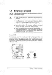
R P4V8X-MX P4V8X-MX Onboard LED SB_PWR ON Standby Power OFF Powered Off 1-4 Chapter 1: Product... switched off mode. The illustration below shows the location of the following precautions before you install motherboard components or change any motherboard settings. • Unplug the power cord from the wall socket before touching any component. •... as the power supply case, before handling components to avoid damaging them . • Whenever you uninstall any motherboard component. Failure to do so may cause severe damage to avoid touching the ICs on a grounded antistatic pad ...
R P4V8X-MX P4V8X-MX Onboard LED SB_PWR ON Standby Power OFF Powered Off 1-4 Chapter 1: Product... switched off mode. The illustration below shows the location of the following precautions before you install motherboard components or change any motherboard settings. • Unplug the power cord from the wall socket before touching any component. •... as the power supply case, before handling components to avoid damaging them . • Whenever you uninstall any motherboard component. Failure to do so may cause severe damage to avoid touching the ICs on a grounded antistatic pad ...

Motherboard DIY Troubleshooting Guide
Page 14
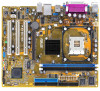
DDR DIMM1 (64 bit, 184-pin module) DDR DIMM2 (64 bit, 184-pin module) ATXPWR FLOPPY 24.5cm(9.6in) 1.5 Motherboard overview 1.5.1 Motherboard layout PS2USBPWR PS/2KBMS T:Mouse B:Keyboard ATX12V COM1 19.6cm(8.0in) Socket 478 Super I/O 4Mb BIOS PARALLEL PORT VGA USB1 USB56 USB2 CPU_FAN Bottom: Top: ... RJ-45 CHA_FAN VIA P4M800 Top:Line In R Center:Line Out Below:Mic In CR2032 3V Lithium Cell CMOS Power CLRTC FP_AUDIO CD AUX PCI1 P4V8X-MX PCI2 VIA VT8237R PLUS AUDIO SPDIF_OUT PCI3 CHASSIS SB_PWR USB78 PANEL SATA2 SATA1 PRI_IDE SEC_IDE ASUS P4V8X-MX Motherboard 1-5
DDR DIMM1 (64 bit, 184-pin module) DDR DIMM2 (64 bit, 184-pin module) ATXPWR FLOPPY 24.5cm(9.6in) 1.5 Motherboard overview 1.5.1 Motherboard layout PS2USBPWR PS/2KBMS T:Mouse B:Keyboard ATX12V COM1 19.6cm(8.0in) Socket 478 Super I/O 4Mb BIOS PARALLEL PORT VGA USB1 USB56 USB2 CPU_FAN Bottom: Top: ... RJ-45 CHA_FAN VIA P4M800 Top:Line In R Center:Line Out Below:Mic In CR2032 3V Lithium Cell CMOS Power CLRTC FP_AUDIO CD AUX PCI1 P4V8X-MX PCI2 VIA VT8237R PLUS AUDIO SPDIF_OUT PCI3 CHASSIS SB_PWR USB78 PANEL SATA2 SATA1 PRI_IDE SEC_IDE ASUS P4V8X-MX Motherboard 1-5
Motherboard DIY Troubleshooting Guide
Page 15
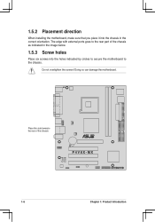
1.5.2 Placement direction When installing the motherboard, make sure that you place it into the chassis in the image below. 1.5.3 Screw holes Place six screws into the holes indicated by circles to secure the motherboard to the rear part of the chassis R P4V8X-MX 1-6 Chapter 1: Product Introduction Doing so can damage the motherboard. Place this side towards-the rear of the chassis as indicated in the correct orientation. Do not overtighten the screws! The edge with external ports goes to the chassis.
1.5.2 Placement direction When installing the motherboard, make sure that you place it into the chassis in the image below. 1.5.3 Screw holes Place six screws into the holes indicated by circles to secure the motherboard to the rear part of the chassis R P4V8X-MX 1-6 Chapter 1: Product Introduction Doing so can damage the motherboard. Place this side towards-the rear of the chassis as indicated in the correct orientation. Do not overtighten the screws! The edge with external ports goes to the chassis.

Motherboard DIY Troubleshooting Guide
Page 16
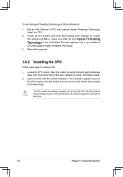
... supported operating system. 5. Make sure to this indicator when orienting the CPU. ASUS P4V8X-MX Motherboard 1-7 This corner is usually indicated with core speeds of the CPU to ensure system stability and performance. 3. This motherboard supports Intel® Pentium® 4 CPUs with Hyper-Threading Technology 2. Under ... Linux 2.4.x (kernel) and later versoins only. For more infformaion on top of less than 1GHz. R P4V8X-MX P4V8X-MX CPU Socket 478 Gold Arrow Notes on Intel Hyper-Threading Technology 1. The Intel Pentium 4/Celeron CPU has a "marked" corner.
... supported operating system. 5. Make sure to this indicator when orienting the CPU. ASUS P4V8X-MX Motherboard 1-7 This corner is usually indicated with core speeds of the CPU to ensure system stability and performance. 3. This motherboard supports Intel® Pentium® 4 CPUs with Hyper-Threading Technology 2. Under ... Linux 2.4.x (kernel) and later versoins only. For more infformaion on top of less than 1GHz. R P4V8X-MX P4V8X-MX CPU Socket 478 Gold Arrow Notes on Intel Hyper-Threading Technology 1. The Intel Pentium 4/Celeron CPU has a "marked" corner.
Motherboard DIY Troubleshooting Guide
Page 17
... 100-degree angle. 2. Power up the system and enter BIOS Setup (see Chapter 4). Locate the CPU socket. To use the Hyper-Threading Technology on this motherboard: 1.
... 100-degree angle. 2. Power up the system and enter BIOS Setup (see Chapter 4). Locate the CPU socket. To use the Hyper-Threading Technology on this motherboard: 1.
Motherboard DIY Troubleshooting Guide
Page 18
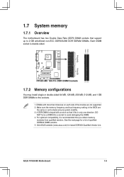
DIMMs with a notch so that it is double-sided. R P4V8X-MX P4V8X-MX 184-Pin DDR DIMM Sockets 1.7.2 Memory configurations You may install single or double-sided 64 MB, 128 MB, 256 MB, 512 MB, and 1 ... Vendor List. A DDR DIMM is keyed with more than 8 devices on each side of qualified DDR333 DIMM vendors. 5. ASUS P4V8X-MX Motherboard 1-9 DIMM1 DIMM2 104 Pins 80 Pins 1.7 System memory 1.7.1 Overview The motherboard has two Double Data Rate (DDR) DIMM sockets that support up to [Auto] ensure system stability. 3. For optimum compatibility, it...
DIMMs with a notch so that it is double-sided. R P4V8X-MX P4V8X-MX 184-Pin DDR DIMM Sockets 1.7.2 Memory configurations You may install single or double-sided 64 MB, 128 MB, 256 MB, 512 MB, and 1 ... Vendor List. A DDR DIMM is keyed with more than 8 devices on each side of qualified DDR333 DIMM vendors. 5. ASUS P4V8X-MX Motherboard 1-9 DIMM1 DIMM2 104 Pins 80 Pins 1.7 System memory 1.7.1 Overview The motherboard has two Double Data Rate (DDR) DIMM sockets that support up to [Auto] ensure system stability. 3. For optimum compatibility, it...
Motherboard DIY Troubleshooting Guide
Page 19
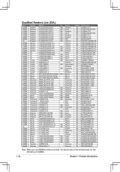
... Twinmos DDR333-256 Twinmos SS TMD7608F8E60B 256MB Twinmos M2G9108A-TT Twinmos SS TMD7608F8E501 Note: When you use 400MHz memory module, the default data of this motherboard run the efficieincy of 333MHz. 1-10 Chapter 1: Product Introduction
... Twinmos DDR333-256 Twinmos SS TMD7608F8E60B 256MB Twinmos M2G9108A-TT Twinmos SS TMD7608F8E501 Note: When you use 400MHz memory module, the default data of this motherboard run the efficieincy of 333MHz. 1-10 Chapter 1: Product Introduction
Motherboard DIY Troubleshooting Guide
Page 20
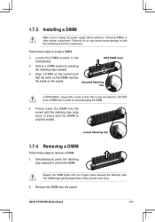
... DIMM. 4. Remove the DIMM from the socket. DDR DIMM notch 2. Firmly insert the DIMM into a socket to both the motherboard and the components. The DIMM might get damaged when it fits in place and the DIMM is keyed with a notch ... other system components. Locate the DIMM sockets in the motherboard. 1.7.3 Installing a DIMM Make sure to unlock the DIMM. Locked Retaining Clip 1.7.4 Removing a DIMM Follow these steps to remove a DIMM. 1. Follow these steps to install a DIMM. 1. ASUS P4V8X-MX Motherboard 1-11 Unlock a DIMM socket by pressing the retaining ...
... DIMM. 4. Remove the DIMM from the socket. DDR DIMM notch 2. Firmly insert the DIMM into a socket to both the motherboard and the components. The DIMM might get damaged when it fits in place and the DIMM is keyed with a notch ... other system components. Locate the DIMM sockets in the motherboard. 1.7.3 Installing a DIMM Make sure to unlock the DIMM. Locked Retaining Clip 1.7.4 Removing a DIMM Follow these steps to remove a DIMM. 1. Follow these steps to install a DIMM. 1. ASUS P4V8X-MX Motherboard 1-11 Unlock a DIMM socket by pressing the retaining ...
Motherboard DIY Troubleshooting Guide
Page 21
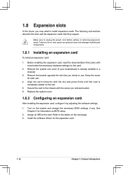
...to unplug the power cord before adding or removing expansion cards. Make sure to the card. Remove the system unit cover (if your motherboard is completely seated on the next page. 3. Align the card connector with the slot and press firmly until the card is already ...). 3. Refer to the chassis with it by adjusting the software settings. 1. 1.8 Expansion slots In the future, you may cause you physical injury and damage motherboard components. 1.8.1 Installing an expansion card To install an expansion card: 1. Failure to do so may need to use . 4. See Chapter 2 for the card...
...to unplug the power cord before adding or removing expansion cards. Make sure to the card. Remove the system unit cover (if your motherboard is completely seated on the next page. 3. Align the card connector with the slot and press firmly until the card is already ...). 3. Refer to the chassis with it by adjusting the software settings. 1. 1.8 Expansion slots In the future, you may cause you physical injury and damage motherboard components. 1.8.1 Installing an expansion card To install an expansion card: 1. Failure to do so may need to use . 4. See Chapter 2 for the card...
Motherboard DIY Troubleshooting Guide
Page 22
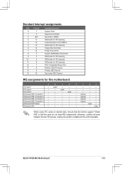
... PCI cards on shared slots, ensure that the drivers support "Share IRQ" or that the cards do not need IRQ assignments; Onboard LAN - - - - shared - - - used - ASUS P4V8X-MX Motherboard 1-13 used - - PCI slot 2 - - shared - - - PCI slot 3 - - - Onboard USB Controller 4 - - - - E F G H - - - - - - - - - - - - - Standard interrupt assignments ... Data Processor Primary IDE Channel Secondary IDE Channel IRQ assignments for this motherboard A B C D PCI slot 1 - used - - - - used Onboard USB Controller 1 - - - - Onboard ...
... PCI cards on shared slots, ensure that the drivers support "Share IRQ" or that the cards do not need IRQ assignments; Onboard LAN - - - - shared - - - used - ASUS P4V8X-MX Motherboard 1-13 used - - PCI slot 2 - - shared - - - PCI slot 3 - - - Onboard USB Controller 4 - - - - E F G H - - - - - - - - - - - - - Standard interrupt assignments ... Data Processor Primary IDE Channel Secondary IDE Channel IRQ assignments for this motherboard A B C D PCI slot 1 - used - - - - used Onboard USB Controller 1 - - - - Onboard ...

Motherboard DIY Troubleshooting Guide
Page 23
The figure shows a LAN card installed on the card golden fingers to ensure that comply with PCI specifications. Note the notches on a PCI slot. 1-14 Chapter 1: Product Introduction R P4V8X-MX Keyed for 1.5v P4V8X-MX Accelerated Graphics Port (AGP) 1.8.4 PCI slots The PCI slots support cards such as a LAN card, SCSI card, USB card, and other cards that they fit into the AGP slot. 1.8.3 AGP slot The motherboard has an Accelerated Graphics Port (AGP) slot that supports +1.5 V 8X AGP graphics card.
The figure shows a LAN card installed on the card golden fingers to ensure that comply with PCI specifications. Note the notches on a PCI slot. 1-14 Chapter 1: Product Introduction R P4V8X-MX Keyed for 1.5v P4V8X-MX Accelerated Graphics Port (AGP) 1.8.4 PCI slots The PCI slots support cards such as a LAN card, SCSI card, USB card, and other cards that they fit into the AGP slot. 1.8.3 AGP slot The motherboard has an Accelerated Graphics Port (AGP) slot that supports +1.5 V 8X AGP graphics card.
Motherboard DIY Troubleshooting Guide
Page 24
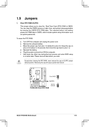
To erase the RTC RAM: a. Keep the cap on CLRTC jumper default position. Clear CMOS 3 2 R CLRTC P4V8X-MX P4V8X-MX Clear RTC RAM Normal (Default) 2 1 ASUS P4V8X-MX Motherboard 1-15 b. d. Except when clearing the RTC RAM, never remove the cap on pins 2-3 for about 5~10 seconds, then move the cap back to clear the ...
To erase the RTC RAM: a. Keep the cap on CLRTC jumper default position. Clear CMOS 3 2 R CLRTC P4V8X-MX P4V8X-MX Clear RTC RAM Normal (Default) 2 1 ASUS P4V8X-MX Motherboard 1-15 b. d. Except when clearing the RTC RAM, never remove the cap on pins 2-3 for about 5~10 seconds, then move the cap back to clear the ...
Motherboard DIY Troubleshooting Guide
Page 26
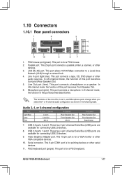
... Rear Speaker Out Front Speaker Out Bass/Center 7. This 9-pin COM1 port is for pointing devices or other VGA-compatible devices. 10. USB 2.0 ports 3 and 4. ASUS P4V8X-MX Motherboard 1-17 1.10 Connectors 1.10.1 Rear panel connectors 1 2 3 4 5 6 11 10 9 8 7 1. This port connects a headphone or a speaker. PS/2 mouse port (green). This 15-pin port is for...
... Rear Speaker Out Front Speaker Out Bass/Center 7. This 9-pin COM1 port is for pointing devices or other VGA-compatible devices. 10. USB 2.0 ports 3 and 4. ASUS P4V8X-MX Motherboard 1-17 1.10 Connectors 1.10.1 Rear panel connectors 1 2 3 4 5 6 11 10 9 8 7 1. This port connects a headphone or a speaker. PS/2 mouse port (green). This 15-pin port is for...


