Motherboard DIY Troubleshooting Guide
Page 8
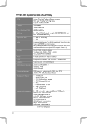
P4V8X-MX Specifications Summary CPU Chipset Front Side Bus (FSB) Memory Expansion Slots VGA Storage Audio LAN USB 2.0 ASUS Special features Overclock Features Back panel I/O ports Internal I/O connectors Socket 478 for Intel Pentium 4/ Celeron processor Intel... FSB frequency adjustable with 1MHz step (SFS) ASUS C.P.R. (CPU Parameter Recall) 1 x Parallel port 1 x Serial (COM1) port 1 x PS/2 Keyboard port (purple) 1 x PS/2 Mouse port (green) 1 x VGA 1 x 6-channel Audio I/O port 4 x USB 2.0/1.1 ports 1 x LAN (RJ-45) port 2 x USB connectors supports additional 4 USB ports CPU/Chassis FAN ...
P4V8X-MX Specifications Summary CPU Chipset Front Side Bus (FSB) Memory Expansion Slots VGA Storage Audio LAN USB 2.0 ASUS Special features Overclock Features Back panel I/O ports Internal I/O connectors Socket 478 for Intel Pentium 4/ Celeron processor Intel... FSB frequency adjustable with 1MHz step (SFS) ASUS C.P.R. (CPU Parameter Recall) 1 x Parallel port 1 x Serial (COM1) port 1 x PS/2 Keyboard port (purple) 1 x PS/2 Mouse port (green) 1 x VGA 1 x 6-channel Audio I/O port 4 x USB 2.0/1.1 ports 1 x LAN (RJ-45) port 2 x USB connectors supports additional 4 USB ports CPU/Chassis FAN ...

Motherboard DIY Troubleshooting Guide
Page 14
... RJ-45 CHA_FAN VIA P4M800 Top:Line In R Center:Line Out Below:Mic In CR2032 3V Lithium Cell CMOS Power CLRTC FP_AUDIO CD AUX PCI1 P4V8X-MX PCI2 VIA VT8237R PLUS AUDIO SPDIF_OUT PCI3 CHASSIS SB_PWR USB78 PANEL SATA2 SATA1 PRI_IDE SEC_IDE ASUS P4V8X-MX Motherboard 1-5
... RJ-45 CHA_FAN VIA P4M800 Top:Line In R Center:Line Out Below:Mic In CR2032 3V Lithium Cell CMOS Power CLRTC FP_AUDIO CD AUX PCI1 P4V8X-MX PCI2 VIA VT8237R PLUS AUDIO SPDIF_OUT PCI3 CHASSIS SB_PWR USB78 PANEL SATA2 SATA1 PRI_IDE SEC_IDE ASUS P4V8X-MX Motherboard 1-5
Motherboard DIY Troubleshooting Guide
Page 22
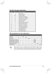
..., making the system unstable and the card inoperable. used - PCI slot 3 - - - Onboard LAN - - - - shared - - - used Onboard USB Controller 1 - - - - used - - - - Onboard AC97 Audio - - - - E F G H - - - - - - - - - - - - - shared - - - Onboard USB Controller 4 - - - - ASUS P4V8X-MX Motherboard 1-13 shared - - - shared - - - - Onboard USB Controller 3 - - - - used - - Standard interrupt assignments IRQ Priority Standard Function 0 1 1 2 2 N/A 3 11 4 12 5 13 6 14 7 15 8 3 9 4 10...
..., making the system unstable and the card inoperable. used - PCI slot 3 - - - Onboard LAN - - - - shared - - - used Onboard USB Controller 1 - - - - used - - - - Onboard AC97 Audio - - - - E F G H - - - - - - - - - - - - - shared - - - Onboard USB Controller 4 - - - - ASUS P4V8X-MX Motherboard 1-13 shared - - - shared - - - - Onboard USB Controller 3 - - - - used - - Standard interrupt assignments IRQ Priority Standard Function 0 1 1 2 2 N/A 3 11 4 12 5 13 6 14 7 15 8 3 9 4 10...
Motherboard DIY Troubleshooting Guide
Page 26
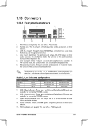
...Out. 6. Video Graphics Adapter port. This 15-pin port is for connecting USB 2.0 devices. 8. This port is for pointing devices or other audio sources. This 25-pin port connects a parallel printer, a scanner, or other VGA-compatible devices. 10. Line In port (light blue). ... headphone or a speaker. Audio 2, 4, or 6-channel configuration Port Headset/2-channel 4-channel Light Blue Lime Pink Line In Line Out Mic In Rear Speaker Out Front Speaker Out Mic In 6-channel Rear Speaker Out Front Speaker Out Bass/Center 7. ASUS P4V8X-MX Motherboard 1-17 These two 4-...
...Out. 6. Video Graphics Adapter port. This 15-pin port is for connecting USB 2.0 devices. 8. This port is for pointing devices or other audio sources. This 25-pin port connects a parallel printer, a scanner, or other VGA-compatible devices. 10. Line In port (light blue). ... headphone or a speaker. Audio 2, 4, or 6-channel configuration Port Headset/2-channel 4-channel Light Blue Lime Pink Line In Line Out Mic In Rear Speaker Out Front Speaker Out Mic In 6-channel Rear Speaker Out Front Speaker Out Bass/Center 7. ASUS P4V8X-MX Motherboard 1-17 These two 4-...
Motherboard DIY Troubleshooting Guide
Page 29
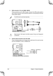
...+ USB_P8USB+5V GND USB_P7+ USB78 USB_P7USB+5V 1 1 Never connect a 1394 cable to a slot opening at the back of the system chassis. R P4V8X-MX CD(Black) Left Audio Channel Ground Ground Right Audio Channel AUX(White) P4V8X-MX Internal Audio Connectors 1-20 Chapter 1: Product Introduction USB connectors (10-1 pin USB56, USB78) These connectors are for USB 2.0 ports. Internal...
...+ USB_P8USB+5V GND USB_P7+ USB78 USB_P7USB+5V 1 1 Never connect a 1394 cable to a slot opening at the back of the system chassis. R P4V8X-MX CD(Black) Left Audio Channel Ground Ground Right Audio Channel AUX(White) P4V8X-MX Internal Audio Connectors 1-20 Chapter 1: Product Introduction USB connectors (10-1 pin USB56, USB78) These connectors are for USB 2.0 ports. Internal...
Motherboard DIY Troubleshooting Guide
Page 30
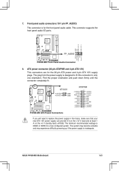
... up if the power supply is for the 20-pin ATX power and 4-pin ATX 12V supply plugs. ASUS P4V8X-MX Motherboard 1-21 This connector supports the front panel audio I/O ports. R P4V8X-MX ATX12V +12V DC +12V DC GND GND ATXPWR +12.0VDC +5VSB PWR_OK GND +5.0VDC GND +5.0VDC GND... +3.3VDC +3.3VDC +5.0VDC +5.0VDC -5.0VDC GND GND GND PS_ON# GND -12.0VDC +3.3VDC P4V8X-MX ATX Power Connectors If you will need...
... up if the power supply is for the 20-pin ATX power and 4-pin ATX 12V supply plugs. ASUS P4V8X-MX Motherboard 1-21 This connector supports the front panel audio I/O ports. R P4V8X-MX ATX12V +12V DC +12V DC GND GND ATXPWR +12.0VDC +5VSB PWR_OK GND +5.0VDC GND +5.0VDC GND... +3.3VDC +3.3VDC +5.0VDC +5.0VDC -5.0VDC GND GND GND PS_ON# GND -12.0VDC +3.3VDC P4V8X-MX ATX Power Connectors If you will need...
Motherboard DIY Troubleshooting Guide
Page 31
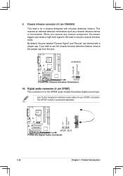
...labeled "Chassis Signal" and "Ground" are shorted with intrusion detection feature. pin SPDIF) This connector is for the S/PDIF audio module that allows digital sound input. • Use 75 ohm impedance matched coaxial cables for your S/PDIF connection. • ... jumper cap from the pins. CHASSIS R P4V8X-MX (Default) P4V8X-MX Chassis Intrusion Connectors 10. Chassis intrusion connector (4-1 pin CHASSIS) This lead is purchased separately. +5VSB_MB Chassis Signal GND +5V SPDIFOUT GND R P4V8X-MX SPDIF_OUT P4V8X-MX Digital Audio Connector 1-22 Chapter 1: Product Introduction This requires...
...labeled "Chassis Signal" and "Ground" are shorted with intrusion detection feature. pin SPDIF) This connector is for the S/PDIF audio module that allows digital sound input. • Use 75 ohm impedance matched coaxial cables for your S/PDIF connection. • ... jumper cap from the pins. CHASSIS R P4V8X-MX (Default) P4V8X-MX Chassis Intrusion Connectors 10. Chassis intrusion connector (4-1 pin CHASSIS) This lead is purchased separately. +5VSB_MB Chassis Signal GND +5V SPDIFOUT GND R P4V8X-MX SPDIF_OUT P4V8X-MX Digital Audio Connector 1-22 Chapter 1: Product Introduction This requires...

Motherboard DIY Troubleshooting Guide
Page 52
...figuration options: [Auto] [Disabled] [Enabled] OnBoard LAN [Enabled] Allows you to enable or disable the OnBoard ACʼ97 Audio CODEC. Configuration options: [Disabled] [Enabled] OnBoard ACʼ97 Audio [Auto] Allows you to enable or disable the OnBoard LAN controller. Configuration options: [Auto] [Disabled] [50°...
...figuration options: [Auto] [Disabled] [Enabled] OnBoard LAN [Enabled] Allows you to enable or disable the OnBoard ACʼ97 Audio CODEC. Configuration options: [Disabled] [Enabled] OnBoard ACʼ97 Audio [Auto] Allows you to enable or disable the OnBoard LAN controller. Configuration options: [Auto] [Disabled] [50°...
Motherboard DIY Troubleshooting Guide
Page 69
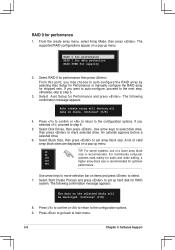
.... A list of valid array block sizes are displayed on a pop-up hard disk for optimum 64K performance. For multimedia computer 16K systems used mainly for audio and video editing, a 32K higher array block size is recommended. Select Start Create Process and press to step 5. 3.
.... A list of valid array block sizes are displayed on a pop-up hard disk for optimum 64K performance. For multimedia computer 16K systems used mainly for audio and video editing, a 32K higher array block size is recommended. Select Start Create Process and press to step 5. 3.

