Motherboard DIY Troubleshooting Guide
Page 1
Motherboard P4V8X-MX User Guide
Motherboard P4V8X-MX User Guide
Motherboard DIY Troubleshooting Guide
Page 3
Contents Notices ...v Safety Information vi About This Guide vii P4V8X-MX Specifications Summary viii Chapter 1: Product Introduction 1.1 Welcome 1-2 1.2 Package Contents 1-2 1.3 Special Features 1-2 1.3.1 Product highlights 1-2 1.3.2 Innovative ASUS features 11.4 Before You Proceed 1-4 1.5 Motherboard Overview 1-5 1.5.1 Motherboard layout 1-5 1.5.2 Placement direction 1-6 1.5.3 Screw holes 1-6 1.6 Central Processing Unit (CPU 1-7 1.6.1 Overview 1-7 1.6.2 Installing the CPU 1-8 1.7 System Memory 1-9 1.7.1 Overview 1-9 1.7.2 Memory configurations...
Contents Notices ...v Safety Information vi About This Guide vii P4V8X-MX Specifications Summary viii Chapter 1: Product Introduction 1.1 Welcome 1-2 1.2 Package Contents 1-2 1.3 Special Features 1-2 1.3.1 Product highlights 1-2 1.3.2 Innovative ASUS features 11.4 Before You Proceed 1-4 1.5 Motherboard Overview 1-5 1.5.1 Motherboard layout 1-5 1.5.2 Placement direction 1-6 1.5.3 Screw holes 1-6 1.6 Central Processing Unit (CPU 1-7 1.6.1 Overview 1-7 1.6.2 Installing the CPU 1-8 1.7 System Memory 1-9 1.7.1 Overview 1-9 1.7.2 Memory configurations...
Motherboard DIY Troubleshooting Guide
Page 6
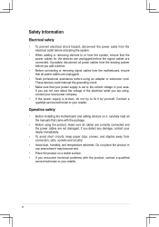
... • Before using the product, make sure all cables are correctly connected and the power cables are not damaged. Operation safety • Before installing the motherboard and adding devices on a stable surface. • If you add a device. • Before connecting or removing signal cables from the... motherboard, ensure that the power cables for the devices are unplugged before using an adapter or extension cord. vi If you are using, contact your ...
... • Before using the product, make sure all cables are correctly connected and the power cables are not damaged. Operation safety • Before installing the motherboard and adding devices on a stable surface. • If you add a device. • Before connecting or removing signal cables from the... motherboard, ensure that the power cables for the devices are unplugged before using an adapter or extension cord. vi If you are using, contact your ...
Motherboard DIY Troubleshooting Guide
Page 7
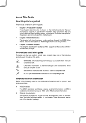
... updates. 1. Conventions used throughout this guide To make sure that you perform certain tasks properly, take note of the motherboard and the new technology it supports. Refer to complete a task. Optional documentation Your product package may include optional documentation,... information to complete a task. It also lists the hardware setup procedures that comes with the motherboard package. ASUS websites The ASUS websites worldwide provide updated information on the motherboard. • Chapter 2: BIOS Information This chapter tells how to perform when installing system components....
... updates. 1. Conventions used throughout this guide To make sure that you perform certain tasks properly, take note of the motherboard and the new technology it supports. Refer to complete a task. Optional documentation Your product package may include optional documentation,... information to complete a task. It also lists the hardware setup procedures that comes with the motherboard package. ASUS websites The ASUS websites worldwide provide updated information on the motherboard. • Chapter 2: BIOS Information This chapter tells how to perform when installing system components....
Motherboard DIY Troubleshooting Guide
Page 10
This chapter describes the motherboard features and the new technologies it supports. 1Product Introduction
This chapter describes the motherboard features and the new technologies it supports. 1Product Introduction

Motherboard DIY Troubleshooting Guide
Page 11
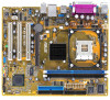
Before you for the following items. Motherboard ASUS P4V8X-MX motherboard Cables 1 x UltraDMA 133/100/66 cable 1 x Serial ATA / Power cable 1 x Floppy Disk Drive cable Accessories I/O shield Application CDs ASUS motherboard support CD Documentation User guide If any of the above items is the mainstream VGA interface specification that enables enhanced graphics performance with the list ...
Before you for the following items. Motherboard ASUS P4V8X-MX motherboard Cables 1 x UltraDMA 133/100/66 cable 1 x Serial ATA / Power cable 1 x Floppy Disk Drive cable Accessories I/O shield Application CDs ASUS motherboard support CD Documentation User guide If any of the above items is the mainstream VGA interface specification that enables enhanced graphics performance with the list ...

Motherboard DIY Troubleshooting Guide
Page 12
... the simple BIOS auto-recovery process. Serial ATA technology Serial ATA is the latest connectivity standard for next generation components and peripherals. ASUS P4V8X-MX Motherboard 1-3 C.P.R. (CPU Parameter Recall) When the system hangs due to overclocking failure, there is faster than current Parallel ATA, while ...give you can convert your favorite photo into a 256-color boot logo for an optional ROM (See page 2-6). ASUS motherboards now enable users to enjoy this motherboard to 40 times faster at 480 MB/s, for easy connectivity and ultra-fast data transfer rate (See pages 1-17 ...
... the simple BIOS auto-recovery process. Serial ATA technology Serial ATA is the latest connectivity standard for next generation components and peripherals. ASUS P4V8X-MX Motherboard 1-3 C.P.R. (CPU Parameter Recall) When the system hangs due to overclocking failure, there is faster than current Parallel ATA, while ...give you can convert your favorite photo into a 256-color boot logo for an optional ROM (See page 2-6). ASUS motherboards now enable users to enjoy this motherboard to 40 times faster at 480 MB/s, for easy connectivity and ultra-fast data transfer rate (See pages 1-17 ...
Motherboard DIY Troubleshooting Guide
Page 13
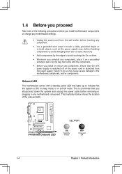
... The illustration below shows the location of the following precautions before you install motherboard components or change any motherboard settings. • Unplug the power cord from the power supply. R P4V8X-MX P4V8X-MX Onboard LED SB_PWR ON Standby Power OFF Powered Off 1-4 Chapter 1: Product ...Introduction Onboard LED The motherboard comes with the component. • Before you install or remove any component, ensure that you...
... The illustration below shows the location of the following precautions before you install motherboard components or change any motherboard settings. • Unplug the power cord from the power supply. R P4V8X-MX P4V8X-MX Onboard LED SB_PWR ON Standby Power OFF Powered Off 1-4 Chapter 1: Product ...Introduction Onboard LED The motherboard comes with the component. • Before you install or remove any component, ensure that you...

Motherboard DIY Troubleshooting Guide
Page 14
DDR DIMM1 (64 bit, 184-pin module) DDR DIMM2 (64 bit, 184-pin module) ATXPWR FLOPPY 24.5cm(9.6in) 1.5 Motherboard overview 1.5.1 Motherboard layout PS2USBPWR PS/2KBMS T:Mouse B:Keyboard ATX12V COM1 19.6cm(8.0in) Socket 478 Super I/O 4Mb BIOS PARALLEL PORT VGA USB1 USB56 USB2 CPU_FAN Bottom: Top: ... RJ-45 CHA_FAN VIA P4M800 Top:Line In R Center:Line Out Below:Mic In CR2032 3V Lithium Cell CMOS Power CLRTC FP_AUDIO CD AUX PCI1 P4V8X-MX PCI2 VIA VT8237R PLUS AUDIO SPDIF_OUT PCI3 CHASSIS SB_PWR USB78 PANEL SATA2 SATA1 PRI_IDE SEC_IDE ASUS P4V8X-MX Motherboard 1-5
DDR DIMM1 (64 bit, 184-pin module) DDR DIMM2 (64 bit, 184-pin module) ATXPWR FLOPPY 24.5cm(9.6in) 1.5 Motherboard overview 1.5.1 Motherboard layout PS2USBPWR PS/2KBMS T:Mouse B:Keyboard ATX12V COM1 19.6cm(8.0in) Socket 478 Super I/O 4Mb BIOS PARALLEL PORT VGA USB1 USB56 USB2 CPU_FAN Bottom: Top: ... RJ-45 CHA_FAN VIA P4M800 Top:Line In R Center:Line Out Below:Mic In CR2032 3V Lithium Cell CMOS Power CLRTC FP_AUDIO CD AUX PCI1 P4V8X-MX PCI2 VIA VT8237R PLUS AUDIO SPDIF_OUT PCI3 CHASSIS SB_PWR USB78 PANEL SATA2 SATA1 PRI_IDE SEC_IDE ASUS P4V8X-MX Motherboard 1-5
Motherboard DIY Troubleshooting Guide
Page 15
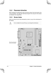
Place this side towards-the rear of the chassis as indicated in the image below. 1.5.3 Screw holes Place six screws into the chassis in the correct orientation. Doing so can damage the motherboard. 1.5.2 Placement direction When installing the motherboard, make sure that you place it into the holes indicated by circles to secure the motherboard to the chassis. Do not overtighten the screws! The edge with external ports goes to the rear part of the chassis R P4V8X-MX 1-6 Chapter 1: Product Introduction
Place this side towards-the rear of the chassis as indicated in the image below. 1.5.3 Screw holes Place six screws into the chassis in the correct orientation. Doing so can damage the motherboard. 1.5.2 Placement direction When installing the motherboard, make sure that you place it into the holes indicated by circles to secure the motherboard to the chassis. Do not overtighten the screws! The edge with external ports goes to the rear part of the chassis R P4V8X-MX 1-6 Chapter 1: Product Introduction

Motherboard DIY Troubleshooting Guide
Page 16
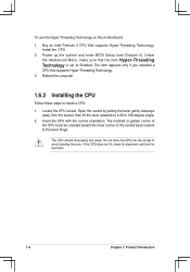
...processors with a notch, and/or a golden square or triangle. If you install Windows® XP Service Pack 1. 4. ASUS P4V8X-MX Motherboard 1-7 Hyper-Threading Technology is recommended that you are using any other operating systems, disable the Hyper-Threading Technology item in ... the Hyper-Threading Technology item in BIOS to this indicator when orienting the CPU. R P4V8X-MX P4V8X-MX CPU Socket 478 Gold Arrow Notes on Intel Hyper-Threading Technology 1. This motherboard supports Intel® Pentium® 4 CPUs with Hyper-Threading Technology 2. The Intel Pentium...
...processors with a notch, and/or a golden square or triangle. If you install Windows® XP Service Pack 1. 4. ASUS P4V8X-MX Motherboard 1-7 Hyper-Threading Technology is recommended that you are using any other operating systems, disable the Hyper-Threading Technology item in ... the Hyper-Threading Technology item in BIOS to this indicator when orienting the CPU. R P4V8X-MX P4V8X-MX CPU Socket 478 Gold Arrow Notes on Intel Hyper-Threading Technology 1. This motherboard supports Intel® Pentium® 4 CPUs with Hyper-Threading Technology 2. The Intel Pentium...
Motherboard DIY Troubleshooting Guide
Page 17
To use the Hyper-Threading Technology on this motherboard: 1. Buy an Intel Pentium 4 CPU that supports Hyper-Threading Technology. 3. The CPU should drop easily into the socket to avoid bending the pins. The notched ...
To use the Hyper-Threading Technology on this motherboard: 1. Buy an Intel Pentium 4 CPU that supports Hyper-Threading Technology. 3. The CPU should drop easily into the socket to avoid bending the pins. The notched ...
Motherboard DIY Troubleshooting Guide
Page 18
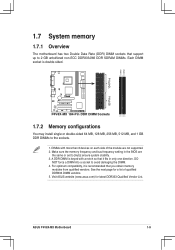
...that you obtain memory modules from qualified vendors. See the next page for latest DDR333 Qualified Vendor List. Visit ASUS website (www.asus.com) for a list of the module are the same or set to the sockets. 1. A DDR DIMM is keyed with ...only one direction. DIMM1 DIMM2 104 Pins 80 Pins 1.7 System memory 1.7.1 Overview The motherboard has two Double Data Rate (DDR) DIMM sockets that support up to avoid damaging the DIMM. 4. ASUS P4V8X-MX Motherboard 1-9 R P4V8X-MX P4V8X-MX 184-Pin DDR DIMM Sockets 1.7.2 Memory configurations You may install single or double...
...that you obtain memory modules from qualified vendors. See the next page for latest DDR333 Qualified Vendor List. Visit ASUS website (www.asus.com) for a list of the module are the same or set to the sockets. 1. A DDR DIMM is keyed with ...only one direction. DIMM1 DIMM2 104 Pins 80 Pins 1.7 System memory 1.7.1 Overview The motherboard has two Double Data Rate (DDR) DIMM sockets that support up to avoid damaging the DIMM. 4. ASUS P4V8X-MX Motherboard 1-9 R P4V8X-MX P4V8X-MX 184-Pin DDR DIMM Sockets 1.7.2 Memory configurations You may install single or double...
Motherboard DIY Troubleshooting Guide
Page 19
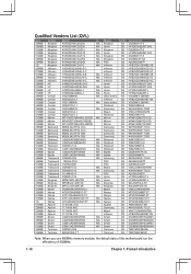
... Twinmos DDR333-256 Twinmos SS TMD7608F8E60B 256MB Twinmos M2G9108A-TT Twinmos SS TMD7608F8E501 Note: When you use 400MHz memory module, the default data of this motherboard run the efficieincy of 333MHz. 1-10 Chapter 1: Product Introduction
... Twinmos DDR333-256 Twinmos SS TMD7608F8E60B 256MB Twinmos M2G9108A-TT Twinmos SS TMD7608F8E501 Note: When you use 400MHz memory module, the default data of this motherboard run the efficieincy of 333MHz. 1-10 Chapter 1: Product Introduction
Motherboard DIY Troubleshooting Guide
Page 20
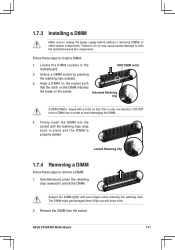
...socket. DO NOT force a DIMM into the socket until the retaining clips snap back in only one direction. ASUS P4V8X-MX Motherboard 1-11 Unlock a DIMM socket by pressing the retaining clips outward. 3. Simultaneously press the retaining clips outward to both the... motherboard and the components. The DIMM might get damaged when it fits in place and the DIMM is properly seated. Locate the DIMM sockets in the motherboard. 1.7.3 Installing a DIMM Make sure to avoid damaging the DIMM...
...socket. DO NOT force a DIMM into the socket until the retaining clips snap back in only one direction. ASUS P4V8X-MX Motherboard 1-11 Unlock a DIMM socket by pressing the retaining clips outward. 3. Simultaneously press the retaining clips outward to both the... motherboard and the components. The DIMM might get damaged when it fits in place and the DIMM is properly seated. Locate the DIMM sockets in the motherboard. 1.7.3 Installing a DIMM Make sure to avoid damaging the DIMM...
Motherboard DIY Troubleshooting Guide
Page 21
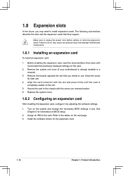
...settings for later use . Install the software drivers for information on the next page. 3. Remove the system unit cover (if your motherboard is completely seated on the system and change the necessary BIOS settings, if any. Secure the card to install expansion cards. Failure to... the documentation that came with the screw you removed earlier. 6. 1.8 Expansion slots In the future, you may cause you physical injury and damage motherboard components. 1.8.1 Installing an expansion card To install an expansion card: 1. Turn on the slot. 5. Keep the screw for the card. 2. The...
...settings for later use . Install the software drivers for information on the next page. 3. Remove the system unit cover (if your motherboard is completely seated on the system and change the necessary BIOS settings, if any. Secure the card to install expansion cards. Failure to... the documentation that came with the screw you removed earlier. 6. 1.8 Expansion slots In the future, you may cause you physical injury and damage motherboard components. 1.8.1 Installing an expansion card To install an expansion card: 1. Turn on the slot. 5. Keep the screw for the card. 2. The...
Motherboard DIY Troubleshooting Guide
Page 22
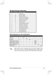
... 1 - - - - Onboard USB Controller 2 - - - - Onboard USB Controller 3 - - - - Onboard USB Controller 4 - - - - shared - - - used - E F G H - - - - - - - - - - - - - ASUS P4V8X-MX Motherboard 1-13 PCI slot 3 - - - Onboard AC97 Audio - - - - shared - - - otherwise, conflicts will arise between the two PCI groups, making the system unstable and the card ... holder for PCI steering PS/2 Compatible Mouse Port Numeric Data Processor Primary IDE Channel Secondary IDE Channel IRQ assignments for this motherboard A B C D PCI slot 1 -
... 1 - - - - Onboard USB Controller 2 - - - - Onboard USB Controller 3 - - - - Onboard USB Controller 4 - - - - shared - - - used - E F G H - - - - - - - - - - - - - ASUS P4V8X-MX Motherboard 1-13 PCI slot 3 - - - Onboard AC97 Audio - - - - shared - - - otherwise, conflicts will arise between the two PCI groups, making the system unstable and the card ... holder for PCI steering PS/2 Compatible Mouse Port Numeric Data Processor Primary IDE Channel Secondary IDE Channel IRQ assignments for this motherboard A B C D PCI slot 1 -

Motherboard DIY Troubleshooting Guide
Page 23
R P4V8X-MX Keyed for 1.5v P4V8X-MX Accelerated Graphics Port (AGP) 1.8.4 PCI slots The PCI slots support cards such as a LAN card, SCSI card, USB card, and other cards that supports +1.5 V 8X AGP graphics card. The figure shows a LAN card installed on the card golden fingers to ensure that they fit into the AGP slot. Note the notches on a PCI slot. 1-14 Chapter 1: Product Introduction 1.8.3 AGP slot The motherboard has an Accelerated Graphics Port (AGP) slot that comply with PCI specifications.
R P4V8X-MX Keyed for 1.5v P4V8X-MX Accelerated Graphics Port (AGP) 1.8.4 PCI slots The PCI slots support cards such as a LAN card, SCSI card, USB card, and other cards that supports +1.5 V 8X AGP graphics card. The figure shows a LAN card installed on the card golden fingers to ensure that they fit into the AGP slot. Note the notches on a PCI slot. 1-14 Chapter 1: Product Introduction 1.8.3 AGP slot The motherboard has an Accelerated Graphics Port (AGP) slot that comply with PCI specifications.
Motherboard DIY Troubleshooting Guide
Page 24
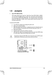
... key during the boot process and enter BIOS setup to pins 1-2. Removing the cap will cause system boot failure! c. Clear CMOS 3 2 R CLRTC P4V8X-MX P4V8X-MX Clear RTC RAM Normal (Default) 2 1 ASUS P4V8X-MX Motherboard 1-15 Move the jumper cap from pins 1-2 (default) to clear the Real Time Clock (RTC) RAM in CMOS, which include system setup information...
... key during the boot process and enter BIOS setup to pins 1-2. Removing the cap will cause system boot failure! c. Clear CMOS 3 2 R CLRTC P4V8X-MX P4V8X-MX Clear RTC RAM Normal (Default) 2 1 ASUS P4V8X-MX Motherboard 1-15 Move the jumper cap from pins 1-2 (default) to clear the Real Time Clock (RTC) RAM in CMOS, which include system setup information...
Motherboard DIY Troubleshooting Guide
Page 26
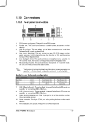
... mode, the function of this port becomes Front Speaker Out. 6. USB 2.0 ports 1 and 2. The functions of this port becomes Surround (Rear Speaker) Out. 5. Serial connector. ASUS P4V8X-MX Motherboard 1-17 This 25-pin port connects a parallel printer, a scanner, or other audio sources. These two 4-pin Universal Serial Bus (USB) ports are available for a PS...
... mode, the function of this port becomes Front Speaker Out. 6. USB 2.0 ports 1 and 2. The functions of this port becomes Surround (Rear Speaker) Out. 5. Serial connector. ASUS P4V8X-MX Motherboard 1-17 This 25-pin port connects a parallel printer, a scanner, or other audio sources. These two 4-pin Universal Serial Bus (USB) ports are available for a PS...


