P4V8X MX Motherboard - Asus
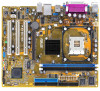
P4V8X MX Motherboard
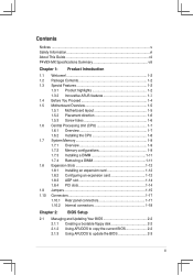
Related Manual Pages


Similar Questions

Motherboard Led Blinking
I have a problem with asus motherboard, when i power up i have notice that the Led blink on trhe mo...
I have a problem with asus motherboard, when i power up i have notice that the Led blink on trhe mo...
(Posted by deepsolutions 11 years ago)

Where Is My Model Number On My Motherboard?
Where is my model number on my motherboard?
Where is my model number on my motherboard?
(Posted by johnfiliceiiii 11 years ago)

Where Do I Find A Motherboard Manual?
I need the manual for an Asus M3A78-EMH HDMI Socket AM2+AMD 780G/Hybrid CrossFireX/HDMI/A&V&...
I need the manual for an Asus M3A78-EMH HDMI Socket AM2+AMD 780G/Hybrid CrossFireX/HDMI/A&V&...
(Posted by ke7hhw 12 years ago)
Related Terms
The following terms were also used when searching for P4V8X MX Motherboard - Asus:- asus motherboard p4v8x-mx
- asus p4v8x
- asus p4v8x driver
- asus p4v8x mx
- asus p4v8x mx audio driver
- asus p4v8x mx bios
- asus p4v8x mx bios update
- asus p4v8x mx download
- asus p4v8x mx driver
- asus p4v8x mx driver download
- asus p4v8x mx drivers
- asus p4v8x mx drivers free download
- asus p4v8x mx manual
- asus p4v8x mx motherboard
- asus p4v8x mx motherboard driver
- asus p4v8x mx motherboard drivers
- asus p4v8x mx motherboard specs
- asus p4v8x mx p4m800
- asus p4v8x mx raid
- asus p4v8x mx raid driver
- asus p4v8x mx raid driver download
- asus p4v8x mx socket 478
- asus p4v8x mx sound
- asus p4v8x mx sound driver download
- asus p4v8x mx specification
- asus p4v8x mx vga driver
- asus p4v8x mx vga drivers
- asus p4v8x mx video driver
- asus p4v8x mx vista drivers
- asus p4v8x xp driver
- asus p4v8x-mx
- asus p4v8x-mx ami bios update
- asus p4v8x-mx audio driver
- asus p4v8x-mx audio driver download
- asus p4v8x-mx audio driver windows 7
- asus p4v8x-mx audio drivers
- asus p4v8x-mx bios
- asus p4v8x-mx bios download
- asus p4v8x-mx bios update
- asus p4v8x-mx connecting switch
- asus p4v8x-mx cpu
- asus p4v8x-mx cpu support
- asus p4v8x-mx driver
- asus p4v8x-mx driver download
- asus p4v8x-mx drivers
- asus p4v8x-mx drivers download
- asus p4v8x-mx drivers for vista*
- asus p4v8x-mx drivers free download
- asus p4v8x-mx drivers support download
- asus p4v8x-mx drivers windows 7
- asus p4v8x-mx drivers xp
- asus p4v8x-mx drivers*
- asus p4v8x-mx freezes up
- asus p4v8x-mx lan drivers
- asus p4v8x-mx manual
- asus p4v8x-mx motherboard
- asus p4v8x-mx motherboard driver download
- asus p4v8x-mx motherboard drivers
- asus p4v8x-mx motherboard drivers free download
- asus p4v8x-mx motherboard manual
- asus p4v8x-mx motherboard problems
- asus p4v8x-mx new
- asus p4v8x-mx overclocking
- asus p4v8x-mx p4m800
- asus p4v8x-mx raid driver
- asus p4v8x-mx ram
- asus p4v8x-mx safe mode
- asus p4v8x-mx socket 478
- asus p4v8x-mx sound driver
- asus p4v8x-mx sound driver download
- asus p4v8x-mx specification
- asus p4v8x-mx vga driver
- asus p4v8x-mx vga driver download
- asus p4v8x-mx vga drivers
- asus p4v8x-mx vga drivers windows 7
- asus p4v8x-mx video driver
- asus p4v8x-mx windows 8
- asus p4v8x-mx windows me drivers
- driver asus p4v8x-mx
- driver p4v8x-mx
- p4v8x asus
- p4v8x audio driver
- p4v8x driver
- p4v8x driver download
- p4v8x drivers
- p4v8x manual
- p4v8x motherboard
- p4v8x motherboard photos
- p4v8x mx
- p4v8x mx asus
- p4v8x mx audio driver
- p4v8x mx audio drivers
- p4v8x mx bios
- p4v8x mx bios update
- p4v8x mx download
- p4v8x mx driver
- p4v8x mx driver audio
- p4v8x mx driver download
- p4v8x mx drivers
- p4v8x mx drivers download
- p4v8x mx drivers free download
- p4v8x mx drivers windows 7
- p4v8x mx drivers windows xp
- p4v8x mx lan driver
- p4v8x mx manual
- p4v8x mx memory support
- p4v8x mx motherboard
- p4v8x mx motherboard driver
- p4v8x mx motherboard drivers
- p4v8x mx motherboard specs
- p4v8x mx overclock
- p4v8x mx p4m800
- p4v8x mx raid
- p4v8x mx raid driver
- p4v8x mx raid driver download
- p4v8x mx socket 478
- p4v8x mx sound
- p4v8x mx sound driver download
- p4v8x mx specification
- p4v8x mx vga driver
- p4v8x mx vga drivers
- p4v8x mx video driver
- p4v8x mx vista drivers
- p4v8x mx windows 7
- p4v8x x bios
- p4v8x x bios update
- p4v8x x driver
- p4v8x x driver download
- p4v8x x driver sound
- p4v8x x drivers
- p4v8x x manual
- p4v8x x motherboard
- p4v8x x sata driver
- p4v8x x windows
- p4v8x-mx
- p4v8x-mx all drivers
- p4v8x-mx ami bios update
- p4v8x-mx asus
- p4v8x-mx asus drivers
- p4v8x-mx asus motherboard
- p4v8x-mx audio
- p4v8x-mx audio driver
- p4v8x-mx audio driver download
- p4v8x-mx audio driver for windows 7
- p4v8x-mx audio driver windows 7
- p4v8x-mx audio driver xp
- p4v8x-mx audio drivers
- p4v8x-mx bios
- p4v8x-mx bios download
- p4v8x-mx bios update
- p4v8x-mx cannot boot up
- p4v8x-mx compatible video card
- p4v8x-mx connecting switch
- p4v8x-mx cpu
- p4v8x-mx cpu support
- p4v8x-mx cpu upgrade
- p4v8x-mx driver
- p4v8x-mx driver download
- p4v8x-mx driver free download
- p4v8x-mx drivers
- p4v8x-mx drivers download
- p4v8x-mx drivers for vista*
- p4v8x-mx drivers for win7
- p4v8x-mx drivers free download
- p4v8x-mx drivers support download
- p4v8x-mx drivers video
- p4v8x-mx drivers windows 7
- p4v8x-mx drivers*
- p4v8x-mx freezes up
- p4v8x-mx lan drivers
- p4v8x-mx manual
- p4v8x-mx memory
- p4v8x-mx memory support
- p4v8x-mx motherboard
- p4v8x-mx motherboard driver download
- p4v8x-mx motherboard drivers
- p4v8x-mx motherboard drivers free download
- p4v8x-mx motherboard manual
- p4v8x-mx motherboard problems
- p4v8x-mx new
- p4v8x-mx not found on cd
- p4v8x-mx overclocking
- p4v8x-mx p4m800
- p4v8x-mx raid controller driver
- p4v8x-mx raid driver
- p4v8x-mx ram
- p4v8x-mx safe mode
- p4v8x-mx sata
- p4v8x-mx server motherboard
- p4v8x-mx socket 478
- p4v8x-mx sound
- p4v8x-mx sound driver
- p4v8x-mx sound driver download
- p4v8x-mx sound drivers
- p4v8x-mx specification
- p4v8x-mx specifications
- p4v8x-mx user manual
- p4v8x-mx very slow
- p4v8x-mx vga driver
- p4v8x-mx vga driver download
- p4v8x-mx vga drivers
- p4v8x-mx vga drivers windows 7
- p4v8x-mx video driver
- p4v8x-mx win 7
- p4v8x-mx windows 7
- p4v8x-mx windows 7 driver
- p4v8x-mx windows 8
- p4v8x-mx windows me drivers
- p4v8x-mx. com
- p4v8x-mx.rom
- p4v8x-x asus bios
- p4v8x-x asus driver
- p4v8x-x asus motherboard driver
- p4v8x-x audio driver
- p4v8x-x audio driver download
- p4v8x-x bios
- p4v8x-x chipset drivers
- p4v8x-x controller video
- p4v8x-x cpu support
- p4v8x-x download
- p4v8x-x driver
- p4v8x-x driver download
- p4v8x-x drivers
- p4v8x-x manual
- p4v8x-x motherboard
- p4v8x-x sata
- p4v8x-x sata problem
- p4v8x-x sata support
- p4v8x-x sound driver
- p4v8x-x sound driver download
- p4v8x-x specification
- p4v8x-x via vt8237 sata 2
- p4v8xmx audio driver
- p4v8xmx audio drivers
- p4v8xmx driver
- p4v8xmx drivers
- p4v8xmx manual
- p4v8xmx+manual