
Service Guide
Page 8
... the Mainboard 117 Replacing the CPU 120 Replacing the Fans 121 Replacing the Thermal Module 123 Replacing the WLAN Module 124 Replacing the TV Tuner Module 125 Replacing the Camera Module 126 Replacing the Power Board 128 Replacing the Inverter Board 129 Replacing the ODD Module 132 ...Replacing the ODD Eject Board 134 Replacing the Audio Board 135 Connect the Card Reader Board 136 Replacing the Touchscreen Board 137 Replacing the Power Supply 139 Replacing the HDD 140 Replacing the Mainboard Shielding ...
... the Mainboard 117 Replacing the CPU 120 Replacing the Fans 121 Replacing the Thermal Module 123 Replacing the WLAN Module 124 Replacing the TV Tuner Module 125 Replacing the Camera Module 126 Replacing the Power Board 128 Replacing the Inverter Board 129 Replacing the ODD Module 132 ...Replacing the ODD Eject Board 134 Replacing the Audio Board 135 Connect the Card Reader Board 136 Replacing the Touchscreen Board 137 Replacing the Power Supply 139 Replacing the HDD 140 Replacing the Mainboard Shielding ...
Service Guide
Page 20
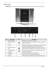
...the power cord into these ports. Plug an line output to an amplifier or entertainment system into this jack for a broadband Internet connection) into this slot. Rear View IMPORTANT:Your computer's hardware options, port locations, and indicators may vary from this connector. Component... Power connector 2 Kensington™ lock slot 3 USB ports 4 Ethernet (network) jack 5 Line-out/Speaker- Allows a TV Tuner to be connected to this connector. Secure your computer to an object by connecting a Kensington cable lock to the system. Plug external hard drives into this jack.
...the power cord into these ports. Plug an line output to an amplifier or entertainment system into this jack for a broadband Internet connection) into this slot. Rear View IMPORTANT:Your computer's hardware options, port locations, and indicators may vary from this connector. Component... Power connector 2 Kensington™ lock slot 3 USB ports 4 Ethernet (network) jack 5 Line-out/Speaker- Allows a TV Tuner to be connected to this connector. Secure your computer to an object by connecting a Kensington cable lock to the system. Plug external hard drives into this jack.
Service Guide
Page 129
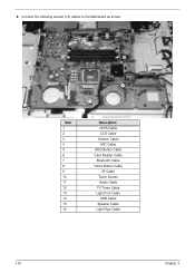
6. Connect the following sixteen (16) cables to the Mainboard as shown. 16 13 11 15 14 12 8 9 7 5 6 4 3 1 2 10 Item 1 2 3 4 5 6 7 8 9 10 11 12 13 14 15 16 Description LVDS Cable CCD Cable Inverter Cable MIC Cable ODD Button Cable Card Reader Cable Bluetooth Cable Home Button Cable IR Cable Touch Screen Audio Cable TV Tuner Cable Light Foot Cable USB Cable Speaker Cable Light Pipe Cable 119 Chapter 3
6. Connect the following sixteen (16) cables to the Mainboard as shown. 16 13 11 15 14 12 8 9 7 5 6 4 3 1 2 10 Item 1 2 3 4 5 6 7 8 9 10 11 12 13 14 15 16 Description LVDS Cable CCD Cable Inverter Cable MIC Cable ODD Button Cable Card Reader Cable Bluetooth Cable Home Button Cable IR Cable Touch Screen Audio Cable TV Tuner Cable Light Foot Cable USB Cable Speaker Cable Light Pipe Cable 119 Chapter 3
Service Guide
Page 135
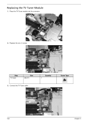
Quantity 1 Screw Type 125 Chapter 3 Replacing the TV Tuner Module 1. Step TV Card Size M2.0*3 3. Replace the one (1) screw. Connect the TV Tuner cable. Place the TV Tuner module into the connector. 2.
Quantity 1 Screw Type 125 Chapter 3 Replacing the TV Tuner Module 1. Step TV Card Size M2.0*3 3. Replace the one (1) screw. Connect the TV Tuner cable. Place the TV Tuner module into the connector. 2.


