Service Guide
Page 16
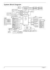
... (Clarkdale option) LVDS Transmitter Chrontel CH7308 LQFP64 SDVOB (No MXM option) SATA HDD(3.5") SATA 0 SATA II SATA ODD SATA 1 eSATA SATA 2 2nd SATA HDD (2.5" x SSD) TOUCH Screen SATA 3 USB 8 USB 2.0 CAREMA with Array MIC BLUE TOOTH USB 4 USB 2 SIDE USB x2 USB 1,5 Lynnfield/ Clarkdale Processor 64-bit/45nm LGA1156 (37.5x37.5mm...
... (Clarkdale option) LVDS Transmitter Chrontel CH7308 LQFP64 SDVOB (No MXM option) SATA HDD(3.5") SATA 0 SATA II SATA ODD SATA 1 eSATA SATA 2 2nd SATA HDD (2.5" x SSD) TOUCH Screen SATA 3 USB 8 USB 2.0 CAREMA with Array MIC BLUE TOOTH USB 4 USB 2 SIDE USB x2 USB 1,5 Lynnfield/ Clarkdale Processor 64-bit/45nm LGA1156 (37.5x37.5mm...
Service Guide
Page 95
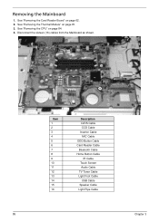
See "Removing the CPU" on page 62. 2. See "Removing the Card Reader Board" on page 84. 4. Removing the Mainboard 1. Disconnect the sixteen (16) cables from the Mainboard as shown. 16 13 11 15 14 12 8 9 7 5 6 10 85 4 3 1 2 Item 1 2 3 4 5 6 7 8 9 10 11 12 13 14 15 16 Description LVDS Cable CCD Cable Inverter Cable MIC Cable ODD Button Cable Card Reader Cable Bluetooth Cable Home Button Cable IR Cable Touch Screen Audio Cable TV Tuner Cable Light Foot Cable USB Cable Speaker Cable Light Pipe Cable Chapter 3 See "Removing the Thermal Module" on page 81. 3.
See "Removing the CPU" on page 62. 2. See "Removing the Card Reader Board" on page 84. 4. Removing the Mainboard 1. Disconnect the sixteen (16) cables from the Mainboard as shown. 16 13 11 15 14 12 8 9 7 5 6 10 85 4 3 1 2 Item 1 2 3 4 5 6 7 8 9 10 11 12 13 14 15 16 Description LVDS Cable CCD Cable Inverter Cable MIC Cable ODD Button Cable Card Reader Cable Bluetooth Cable Home Button Cable IR Cable Touch Screen Audio Cable TV Tuner Cable Light Foot Cable USB Cable Speaker Cable Light Pipe Cable Chapter 3 See "Removing the Thermal Module" on page 81. 3.
Service Guide
Page 104
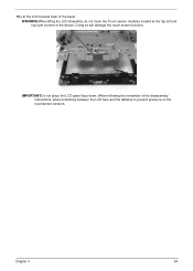
When following the remainder of the device. Doing so will damage the touch screen function. WARNING:When lifting the LCD Assembly, do not touch the Touch sensor modules located at the top left and top right corners of the disassembly instructions, place something between the LCD face and the tabletop to prevent pressure on the touchscreen sensors. IMPORTANT:Do not place the LCD panel face down. 15. Chapter 3 94 Lift the LCD bracket clear of the bezel.
When following the remainder of the device. Doing so will damage the touch screen function. WARNING:When lifting the LCD Assembly, do not touch the Touch sensor modules located at the top left and top right corners of the disassembly instructions, place something between the LCD face and the tabletop to prevent pressure on the touchscreen sensors. IMPORTANT:Do not place the LCD panel face down. 15. Chapter 3 94 Lift the LCD bracket clear of the bezel.
Service Guide
Page 129
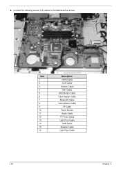
Connect the following sixteen (16) cables to the Mainboard as shown. 16 13 11 15 14 12 8 9 7 5 6 4 3 1 2 10 Item 1 2 3 4 5 6 7 8 9 10 11 12 13 14 15 16 Description LVDS Cable CCD Cable Inverter Cable MIC Cable ODD Button Cable Card Reader Cable Bluetooth Cable Home Button Cable IR Cable Touch Screen Audio Cable TV Tuner Cable Light Foot Cable USB Cable Speaker Cable Light Pipe Cable 119 Chapter 3 6.
Connect the following sixteen (16) cables to the Mainboard as shown. 16 13 11 15 14 12 8 9 7 5 6 4 3 1 2 10 Item 1 2 3 4 5 6 7 8 9 10 11 12 13 14 15 16 Description LVDS Cable CCD Cable Inverter Cable MIC Cable ODD Button Cable Card Reader Cable Bluetooth Cable Home Button Cable IR Cable Touch Screen Audio Cable TV Tuner Cable Light Foot Cable USB Cable Speaker Cable Light Pipe Cable 119 Chapter 3 6.


