
Service Guide
Page 8
... 81 Removing the Fans 82 Removing the CPU 84 Removing the Mainboard 85 Removing the Frame 89 Removing the LCD Panel 95 Removing the Bluetooth Module 97 Removing the IR Board 98 Removing the Home Button Board 100 Removing the USB Board 101 Removing the Speakers 103 Removing the ...the Antennas 105 Replacing the Speakers 106 Replacing the USB Board 107 Replacing the IR Board 108 Replacing the Home Button Board 109 Replacing the Bluetooth Module 110 Replacing the LCD Panel in the Frame 111 Replacing the Frame 113 Replacing the Mainboard 117 Replacing the CPU 120 Replacing the ...
... 81 Removing the Fans 82 Removing the CPU 84 Removing the Mainboard 85 Removing the Frame 89 Removing the LCD Panel 95 Removing the Bluetooth Module 97 Removing the IR Board 98 Removing the Home Button Board 100 Removing the USB Board 101 Removing the Speakers 103 Removing the ...the Antennas 105 Replacing the Speakers 106 Replacing the USB Board 107 Replacing the IR Board 108 Replacing the Home Button Board 109 Replacing the Bluetooth Module 110 Replacing the LCD Panel in the Frame 111 Replacing the Frame 113 Replacing the Mainboard 117 Replacing the CPU 120 Replacing the ...
Service Guide
Page 14
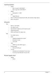
Communication • WLAN: • 802.11 b/g Wi-Fi CERTIFIED™ • 802.11 b/g/n Wi-Fi CERTIFIED™ • WPAN: • Bluetooth® 2.1 + EDR • LAN: • Gigabit Ethernet • Built-in 1 MP high-def webcam with 1280 x 800 resolution image capture • Built-in microphone I/O ports ...
Communication • WLAN: • 802.11 b/g Wi-Fi CERTIFIED™ • 802.11 b/g/n Wi-Fi CERTIFIED™ • WPAN: • Bluetooth® 2.1 + EDR • LAN: • Gigabit Ethernet • Built-in 1 MP high-def webcam with 1280 x 800 resolution image capture • Built-in microphone I/O ports ...
Service Guide
Page 28
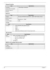
... 18 Chapter 1 Keyboard Controller Item Controller Total number of keypads Windows logo key Hotkeys Specification IT8512E/NX-L embedded Bluetooth Item Chipset Data throughput Protocol Connector type Specification Broadcom BCM2046, Bluetooth2.1 + EDR, USB interface module Bluetooth 2.1 + EDR USB TV Tuner Item TV Tuner Specification • ATSC/QAM/HRC/IRC/Standard Cable • DVB...
... 18 Chapter 1 Keyboard Controller Item Controller Total number of keypads Windows logo key Hotkeys Specification IT8512E/NX-L embedded Bluetooth Item Chipset Data throughput Protocol Connector type Specification Broadcom BCM2046, Bluetooth2.1 + EDR, USB interface module Bluetooth 2.1 + EDR USB TV Tuner Item TV Tuner Specification • ATSC/QAM/HRC/IRC/Standard Cable • DVB...
Service Guide
Page 52
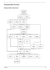
... Remove Mainboard Remove USB Board Remove IR Receiver Remove Frame Remove LCD Panel Remove Antennas Remove Speakers Remove Home Button Board Remove Power Board Remove Bluetooth Module Remove Webcam Chapter 3 42
... Remove Mainboard Remove USB Board Remove IR Receiver Remove Frame Remove LCD Panel Remove Antennas Remove Speakers Remove Home Button Board Remove Power Board Remove Bluetooth Module Remove Webcam Chapter 3 42
Service Guide
Page 95
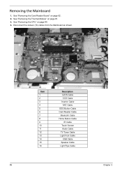
Disconnect the sixteen (16) cables from the Mainboard as shown. 16 13 11 15 14 12 8 9 7 5 6 10 85 4 3 1 2 Item 1 2 3 4 5 6 7 8 9 10 11 12 13 14 15 16 Description LVDS Cable CCD Cable Inverter Cable MIC Cable ODD Button Cable Card Reader Cable Bluetooth Cable Home Button Cable IR Cable Touch Screen Audio Cable TV Tuner Cable Light Foot Cable USB Cable Speaker Cable Light Pipe Cable Chapter 3 See "Removing the CPU" on page 81. 3. See "Removing the Thermal Module" on page 84. 4. Removing the Mainboard 1. See "Removing the Card Reader Board" on page 62. 2.
Disconnect the sixteen (16) cables from the Mainboard as shown. 16 13 11 15 14 12 8 9 7 5 6 10 85 4 3 1 2 Item 1 2 3 4 5 6 7 8 9 10 11 12 13 14 15 16 Description LVDS Cable CCD Cable Inverter Cable MIC Cable ODD Button Cable Card Reader Cable Bluetooth Cable Home Button Cable IR Cable Touch Screen Audio Cable TV Tuner Cable Light Foot Cable USB Cable Speaker Cable Light Pipe Cable Chapter 3 See "Removing the CPU" on page 81. 3. See "Removing the Thermal Module" on page 84. 4. Removing the Mainboard 1. See "Removing the Card Reader Board" on page 62. 2.

Service Guide
Page 107
Lift the Bluetooth module off of the bezel. 3. Removing the Bluetooth Module 1. See "Removing the Bluetooth Module" on page 97. 2. Disconnect the Bluetooth cable. 97 Chapter 3
Lift the Bluetooth module off of the bezel. 3. Removing the Bluetooth Module 1. See "Removing the Bluetooth Module" on page 97. 2. Disconnect the Bluetooth cable. 97 Chapter 3

Service Guide
Page 120
3. Connect the Bluetooth cable to the bezel. Adhere the Bluetooth module to the Bluetooth Module. 2. Connect the home button board cable. Chapter 3 110 Replacing the Bluetooth Module 1.
3. Connect the Bluetooth cable to the bezel. Adhere the Bluetooth module to the Bluetooth Module. 2. Connect the home button board cable. Chapter 3 110 Replacing the Bluetooth Module 1.
Service Guide
Page 129
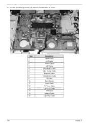
6. Connect the following sixteen (16) cables to the Mainboard as shown. 16 13 11 15 14 12 8 9 7 5 6 4 3 1 2 10 Item 1 2 3 4 5 6 7 8 9 10 11 12 13 14 15 16 Description LVDS Cable CCD Cable Inverter Cable MIC Cable ODD Button Cable Card Reader Cable Bluetooth Cable Home Button Cable IR Cable Touch Screen Audio Cable TV Tuner Cable Light Foot Cable USB Cable Speaker Cable Light Pipe Cable 119 Chapter 3
6. Connect the following sixteen (16) cables to the Mainboard as shown. 16 13 11 15 14 12 8 9 7 5 6 4 3 1 2 10 Item 1 2 3 4 5 6 7 8 9 10 11 12 13 14 15 16 Description LVDS Cable CCD Cable Inverter Cable MIC Cable ODD Button Cable Card Reader Cable Bluetooth Cable Home Button Cable IR Cable Touch Screen Audio Cable TV Tuner Cable Light Foot Cable USB Cable Speaker Cable Light Pipe Cable 119 Chapter 3
Service Guide
Page 185
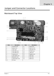
Jumper and Connector Locations Mainboard Top View 34 Chapter 5 19 2 1 5 6 18 17 7 16 8 15 Item 1 2 3 4 5 6 7 8 9 10 9 10 Description Iinverter conn power conn LCD conn GPU FAN conn CPU FAN conn camera conn card reader conn Bluetooth conn Home button conn IR conn Item 11 12 13 14 15 16 17 18 19 11 12 13 14 Description Audio conn light foot conn light pipe conn B-CAS conn USB conn Speaker conn PSU SYS PSU CPU SSD conn Chapter 5 175
Jumper and Connector Locations Mainboard Top View 34 Chapter 5 19 2 1 5 6 18 17 7 16 8 15 Item 1 2 3 4 5 6 7 8 9 10 9 10 Description Iinverter conn power conn LCD conn GPU FAN conn CPU FAN conn camera conn card reader conn Bluetooth conn Home button conn IR conn Item 11 12 13 14 15 16 17 18 19 11 12 13 14 Description Audio conn light foot conn light pipe conn B-CAS conn USB conn Speaker conn PSU SYS PSU CPU SSD conn Chapter 5 175


