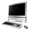
Service Guide
Page 7
... Board 65 Removing the ODD 67 69 Removing the Inverter Board 70 Removing the Home Button Board 73 Removing the Camera Module 75 Removing the TV Tuner Module 77 Removing the Wireless LAN Module 79 VII
... Board 65 Removing the ODD 67 69 Removing the Inverter Board 70 Removing the Home Button Board 73 Removing the Camera Module 75 Removing the TV Tuner Module 77 Removing the Wireless LAN Module 79 VII

Service Guide
Page 8
... 113 Replacing the Mainboard 117 Replacing the CPU 120 Replacing the Fans 121 Replacing the Thermal Module 123 Replacing the WLAN Module 124 Replacing the TV Tuner Module 125 Replacing the Camera Module 126 Replacing the Power Board 128 Replacing the Inverter Board 129 Replacing the ODD Module 132 Replacing the ODD...
... 113 Replacing the Mainboard 117 Replacing the CPU 120 Replacing the Fans 121 Replacing the Thermal Module 123 Replacing the WLAN Module 124 Replacing the TV Tuner Module 125 Replacing the Camera Module 126 Replacing the Power Board 128 Replacing the Inverter Board 129 Replacing the ODD Module 132 Replacing the ODD...
Service Guide
Page 13
... Duo™ TV-tuner Hybrid TV-tuner supporting worldwide analog/DVB-T (Digital Video Broadcasting-Terrestrial) • TV-tuner I/O: • AIO platform • RF-in Hybrid TV-tuner supporting worldwide analog and ATSC (Advanced Television Systems Committee) • TV-tuner I/O: • AIO platform • RF-in Digital TV-tuner supporting ISDB-T/BS/CS • TV-tuner I/O: • Tower platform • RF-in Hybrid TV-tuner supporting DMB...
... Duo™ TV-tuner Hybrid TV-tuner supporting worldwide analog/DVB-T (Digital Video Broadcasting-Terrestrial) • TV-tuner I/O: • AIO platform • RF-in Hybrid TV-tuner supporting worldwide analog and ATSC (Advanced Television Systems Committee) • TV-tuner I/O: • AIO platform • RF-in Digital TV-tuner supporting ISDB-T/BS/CS • TV-tuner I/O: • Tower platform • RF-in Hybrid TV-tuner supporting DMB...
Service Guide
Page 14
.../line-out jack • Microphone-in jack • Line-in jack Video • HDMI™ port with HDCP support Communication • Ethernet (RJ-45) port TV-tuner • IR blaster port (bundled with TV-tuner card) • TV-tuner port (bundled with TV-tuner card) Power Supply Unit • Adapter • 250 W 4 Chapter 1
.../line-out jack • Microphone-in jack • Line-in jack Video • HDMI™ port with HDCP support Communication • Ethernet (RJ-45) port TV-tuner • IR blaster port (bundled with TV-tuner card) • TV-tuner port (bundled with TV-tuner card) Power Supply Unit • Adapter • 250 W 4 Chapter 1
Service Guide
Page 16
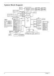
... RTS5159-GR) CLOCK Generator CK505 32.768KHz USB 2.0 LPC PCIE 2 USB 10 Mini PCIE1 WLAN CNN 802.11 b/g/n 3G/WiMax PCIE 3 USB 12 Mini PCIE2 TV Tuner CARD CNN B-CAS CNN RTC Battery Fan CNN Reset Circuit Brightness Control LED Indicator REAR USB x4 USB 0,9,11,13 AUDIO AMP MAX9736BETJ+ QFN32 AUDIO...
... RTS5159-GR) CLOCK Generator CK505 32.768KHz USB 2.0 LPC PCIE 2 USB 10 Mini PCIE1 WLAN CNN 802.11 b/g/n 3G/WiMax PCIE 3 USB 12 Mini PCIE2 TV Tuner CARD CNN B-CAS CNN RTC Battery Fan CNN Reset Circuit Brightness Control LED Indicator REAR USB x4 USB 0,9,11,13 AUDIO AMP MAX9736BETJ+ QFN32 AUDIO...
Service Guide
Page 20
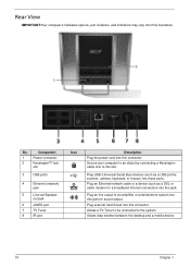
.... Allows data transfer between the desktop and a mobile device. 10 Chapter 1 Plug external hard drives into this jack. Allows a TV Tuner to be connected to an amplifier or entertainment system into this connector. Secure your computer to an object by connecting a Kensington cable lock... to this illustration. out jack 6 eSATA port 7 TV Tuner 8 IR port Icon Description Plug the power cord into this jack for a broadband Internet connection) into these ports. Plug an line...
.... Allows data transfer between the desktop and a mobile device. 10 Chapter 1 Plug external hard drives into this jack. Allows a TV Tuner to be connected to an amplifier or entertainment system into this connector. Secure your computer to an object by connecting a Kensington cable lock... to this illustration. out jack 6 eSATA port 7 TV Tuner 8 IR port Icon Description Plug the power cord into this jack for a broadband Internet connection) into these ports. Plug an line...
Service Guide
Page 28
... throughput Protocol Connector type Specification Broadcom BCM2046, Bluetooth2.1 + EDR, USB interface module Bluetooth 2.1 + EDR USB TV Tuner Item TV Tuner Specification • ATSC/QAM/HRC/IRC/Standard Cable • DVB-T • ISDB-T • DMB-T/H • Meets Microsoft Media Center TV Tuner requirements VGA Controller Item VGA Controller Specifications • INTEL GL40/GM45 Internal Graphics • Direct...
... throughput Protocol Connector type Specification Broadcom BCM2046, Bluetooth2.1 + EDR, USB interface module Bluetooth 2.1 + EDR USB TV Tuner Item TV Tuner Specification • ATSC/QAM/HRC/IRC/Standard Cable • DVB-T • ISDB-T • DMB-T/H • Meets Microsoft Media Center TV Tuner requirements VGA Controller Item VGA Controller Specifications • INTEL GL40/GM45 Internal Graphics • Direct...
Service Guide
Page 53
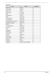
Screw List Step Stand Cover Stand Hinge Rear Cover Audio Board HDD HDD Bracket ODD ODD Brackets Inverter Board Touchscreen Control Board Mainboard Shielding WLAN TV Tuner Module VGA Card Fan Mainboard USB Board IR Receiver Frame LCD Panel Power Board Camera Antennas Speakers Screw M2.5*4 M4*6 Ni M2.5*7 M2.5*4 Ni M2.5*4 Ni M3*4 Ni M2.5*4 Ni M2*2.5 Ni M2.5*4 Ni M2.5*4 Ni M2.5*4 Ni M2*3 M2.5*4 Ni M2.5*4 Ni M2.5*5 Ni M2.5*4 Ni M2.5*4 Ni M2*3 M2.5*4 Ni M3*4 M2.5*4 Ni M2*3 M1.7*4 M2.5*4.0-I(NYLOK)IRON Quantity 2 4 4 2 2 4 2 4 2 2 7 1 1 4 3 1 2 1 15 4 2 2 2 6 43 Chapter 3
Screw List Step Stand Cover Stand Hinge Rear Cover Audio Board HDD HDD Bracket ODD ODD Brackets Inverter Board Touchscreen Control Board Mainboard Shielding WLAN TV Tuner Module VGA Card Fan Mainboard USB Board IR Receiver Frame LCD Panel Power Board Camera Antennas Speakers Screw M2.5*4 M4*6 Ni M2.5*7 M2.5*4 Ni M2.5*4 Ni M3*4 Ni M2.5*4 Ni M2*2.5 Ni M2.5*4 Ni M2.5*4 Ni M2.5*4 Ni M2*3 M2.5*4 Ni M2.5*4 Ni M2.5*5 Ni M2.5*4 Ni M2.5*4 Ni M2*3 M2.5*4 Ni M3*4 M2.5*4 Ni M2*3 M1.7*4 M2.5*4.0-I(NYLOK)IRON Quantity 2 4 4 2 2 4 2 4 2 2 7 1 1 4 3 1 2 1 15 4 2 2 2 6 43 Chapter 3
Service Guide
Page 87
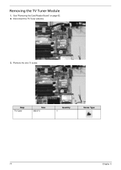
Step TV Card Size M2.0*3 Quantity 1 Screw Type 77 Chapter 3 Removing the TV Tuner Module 1. Disconnect the TV Tuner antenna. 3. See "Removing the Card Reader Board" on page 62. 2. Remove the one (1) screw.
Step TV Card Size M2.0*3 Quantity 1 Screw Type 77 Chapter 3 Removing the TV Tuner Module 1. Disconnect the TV Tuner antenna. 3. See "Removing the Card Reader Board" on page 62. 2. Remove the one (1) screw.
Service Guide
Page 95
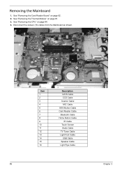
Disconnect the sixteen (16) cables from the Mainboard as shown. 16 13 11 15 14 12 8 9 7 5 6 10 85 4 3 1 2 Item 1 2 3 4 5 6 7 8 9 10 11 12 13 14 15 16 Description LVDS Cable CCD Cable Inverter Cable MIC Cable ODD Button Cable Card Reader Cable Bluetooth Cable Home Button Cable IR Cable Touch Screen Audio Cable TV Tuner Cable Light Foot Cable USB Cable Speaker Cable Light Pipe Cable Chapter 3 See "Removing the Thermal Module" on page 84. 4. See "Removing the CPU" on page 81. 3. Removing the Mainboard 1. See "Removing the Card Reader Board" on page 62. 2.
Disconnect the sixteen (16) cables from the Mainboard as shown. 16 13 11 15 14 12 8 9 7 5 6 10 85 4 3 1 2 Item 1 2 3 4 5 6 7 8 9 10 11 12 13 14 15 16 Description LVDS Cable CCD Cable Inverter Cable MIC Cable ODD Button Cable Card Reader Cable Bluetooth Cable Home Button Cable IR Cable Touch Screen Audio Cable TV Tuner Cable Light Foot Cable USB Cable Speaker Cable Light Pipe Cable Chapter 3 See "Removing the Thermal Module" on page 84. 4. See "Removing the CPU" on page 81. 3. Removing the Mainboard 1. See "Removing the Card Reader Board" on page 62. 2.
Service Guide
Page 129
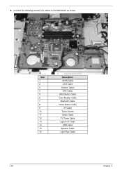
Connect the following sixteen (16) cables to the Mainboard as shown. 16 13 11 15 14 12 8 9 7 5 6 4 3 1 2 10 Item 1 2 3 4 5 6 7 8 9 10 11 12 13 14 15 16 Description LVDS Cable CCD Cable Inverter Cable MIC Cable ODD Button Cable Card Reader Cable Bluetooth Cable Home Button Cable IR Cable Touch Screen Audio Cable TV Tuner Cable Light Foot Cable USB Cable Speaker Cable Light Pipe Cable 119 Chapter 3 6.
Connect the following sixteen (16) cables to the Mainboard as shown. 16 13 11 15 14 12 8 9 7 5 6 4 3 1 2 10 Item 1 2 3 4 5 6 7 8 9 10 11 12 13 14 15 16 Description LVDS Cable CCD Cable Inverter Cable MIC Cable ODD Button Cable Card Reader Cable Bluetooth Cable Home Button Cable IR Cable Touch Screen Audio Cable TV Tuner Cable Light Foot Cable USB Cable Speaker Cable Light Pipe Cable 119 Chapter 3 6.
Service Guide
Page 135
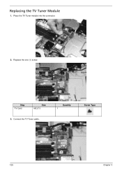
Step TV Card Size M2.0*3 3. Connect the TV Tuner cable. Place the TV Tuner module into the connector. 2. Quantity 1 Screw Type 125 Chapter 3 Replacing the TV Tuner Module 1. Replace the one (1) screw.
Step TV Card Size M2.0*3 3. Connect the TV Tuner cable. Place the TV Tuner module into the connector. 2. Quantity 1 Screw Type 125 Chapter 3 Replacing the TV Tuner Module 1. Replace the one (1) screw.


