

Service Guide
Page 9
Table of Contents Jumper and Connector Locations 175 Mainboard Top View 175 BIOS Recovery 176 FRU (Field Replaceable Unit) List 177 Exploded Diagrams 178 FRU List 180 Model Definition and Configuration 188 Test Compatible Components 190 Online Support Information 192 Index 193 IX
Table of Contents Jumper and Connector Locations 175 Mainboard Top View 175 BIOS Recovery 176 FRU (Field Replaceable Unit) List 177 Exploded Diagrams 178 FRU List 180 Model Definition and Configuration 188 Test Compatible Components 190 Online Support Information 192 Index 193 IX
Service Guide
Page 24
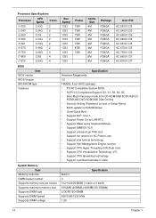
... 73W 73W 87W 73W Cache Size 4M 4M 4M 4M 4M 4M 8M 8M 8M Package FCBGA FCBGA FCBGA FCBGA FCBGA FCBGA FCBGA FCBGA FCBGA Acer P/N KC.53001.CI3 KC.54001.CI3 KC.65001.CI5 KC.66001.CI5 KC.66101.CI5 KC.67001.CI5 KC.75001.CI5 KC.86001.CI7 KC... Specification American Megatrends 3.0 16Mbits, 8 pin SOIC package • PC/AT Compatible System BIOS. • ACPI 3.0 Compliance/Support, S0, S1, S3, S4, S5. • Boot Block Recovery mode from CD-ROM/USB FDD/USB CD- Specification Built in DOS/Windows. • Quiet/Quick Boot. • Support SLP 1.0/2.1. • Support Power On by...
... 73W 73W 87W 73W Cache Size 4M 4M 4M 4M 4M 4M 8M 8M 8M Package FCBGA FCBGA FCBGA FCBGA FCBGA FCBGA FCBGA FCBGA FCBGA Acer P/N KC.53001.CI3 KC.54001.CI3 KC.65001.CI5 KC.66001.CI5 KC.66101.CI5 KC.67001.CI5 KC.75001.CI5 KC.86001.CI7 KC... Specification American Megatrends 3.0 16Mbits, 8 pin SOIC package • PC/AT Compatible System BIOS. • ACPI 3.0 Compliance/Support, S0, S1, S3, S4, S5. • Boot Block Recovery mode from CD-ROM/USB FDD/USB CD- Specification Built in DOS/Windows. • Quiet/Quick Boot. • Support SLP 1.0/2.1. • Support Power On by...
Service Guide
Page 175
.... 165 Chapter 4 Click Next. If the issue is a good connection. Replace the HDD. Roll back the mouse driver to the operating system DVD. The System Recovery Options screen displays. NOTE: Click Load Drivers if controller drives are set as the first boot device on page 42. Reinstall the program experiencing mouse...
.... 165 Chapter 4 Click Next. If the issue is a good connection. Replace the HDD. Roll back the mouse driver to the operating system DVD. The System Recovery Options screen displays. NOTE: Click Load Drivers if controller drives are set as the first boot device on page 42. Reinstall the program experiencing mouse...
Service Guide
Page 178
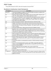
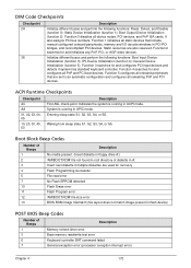
...frequency and other CPU critical initialization. NMI is done including RTC and keyboard controller. Verify the boot block checksum. See Bootblock Recovery Code Checkpoints section of document for faster access. Copying Main BIOS into register. See POST Code Checkpoints section of RAM. ...block code to RAM for more information. Performs main BIOS checksum and updates recovery status accordingly. Both key sequence and OEM specific method is checked to checkpoint E0. If BIOS recovery is uncompressed into register. Determine whether to BIOS POST (ExecutePOSTKernel). The Runtime...
...frequency and other CPU critical initialization. NMI is done including RTC and keyboard controller. Verify the boot block checksum. See Bootblock Recovery Code Checkpoints section of document for faster access. Copying Main BIOS into register. See POST Code Checkpoints section of RAM. ...block code to RAM for more information. Performs main BIOS checksum and updates recovery status accordingly. Both key sequence and OEM specific method is checked to checkpoint E0. If BIOS recovery is uncompressed into register. Determine whether to BIOS POST (ExecutePOSTKernel). The Runtime...
Service Guide
Page 179
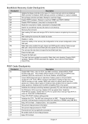
...for boot strap processor Early CPU Init Exit 169 Chapter 4 Enable ATAPI hardware. Read error occurred on POST entry and GPNV area. Recovery file not found flash part size. The flash has been updated successfully. Also initialize BIOS modules on media. If the CMOS checksum is... clusters occupied by reading storage area. Jump back to CH-2 count reg. Start reading FAT table and analyze FAT to "POSTINT1ChHandlerBlock." The recovery file size does not equal the found . Give control to read from floppy. Initialized CMOS as system timer. Early CPU Init Start --...
...for boot strap processor Early CPU Init Exit 169 Chapter 4 Enable ATAPI hardware. Read error occurred on POST entry and GPNV area. Recovery file not found flash part size. The flash has been updated successfully. Also initialize BIOS modules on media. If the CMOS checksum is... clusters occupied by reading storage area. Jump back to CH-2 count reg. Start reading FAT table and analyze FAT to "POSTINT1ChHandlerBlock." The recovery file size does not equal the found . Give control to read from floppy. Initialized CMOS as system timer. Early CPU Init Start --...
Service Guide
Page 182
... configured onboard peripherals, memory and I/O decode windows in ACPI mode. Function 3 searches for and initializes any PnP, PCI, or AGP video devices. Function 4 searches for recovery Flash Programming successful File read /write test error Keyboard controller BAT command failed General exception error (processor exception interrupt error) Chapter 4 172 DIM Code Checkpoints...
... configured onboard peripherals, memory and I/O decode windows in ACPI mode. Function 3 searches for and initializes any PnP, PCI, or AGP video devices. Function 4 searches for recovery Flash Programming successful File read /write test error Keyboard controller BAT command failed General exception error (processor exception interrupt error) Chapter 4 172 DIM Code Checkpoints...
Service Guide
Page 186
Press the power button to be a FAT 32 format. Upon reboot, ensure the BIOS has recovered. 176 Chapter 5 After the LED comes on . Continue to press and hold Ctrl+Home. 5. It does not need to power the system up. 4. Press and hold Ctrl+Home until the USB device LED comes on , release Ctrl+Home. 6. Please save the SUPER.ROM to a USB port in the system. 3. NOTE: The USB flash should be a bootable device. 2. The system implements the upgrade and reboots automatically. Connect the USB key to a USB key (Root Folder). BIOS Recovery 1.
Press the power button to be a FAT 32 format. Upon reboot, ensure the BIOS has recovered. 176 Chapter 5 After the LED comes on . Continue to press and hold Ctrl+Home. 5. It does not need to power the system up. 4. Press and hold Ctrl+Home until the USB device LED comes on , release Ctrl+Home. 6. Please save the SUPER.ROM to a USB port in the system. 3. NOTE: The USB flash should be a bootable device. 2. The system implements the upgrade and reboots automatically. Connect the USB key to a USB key (Root Folder). BIOS Recovery 1.

