Service Guide
Page 7
... DOS Flash Utility 37 Win Flash Utility 38 Using DMI Tools 39 Machine Disassembly and Replacement 40 Disassembly Requirements 40 General Information 40 Pre-disassembly Instructions 40 Disassembly Process 42 Disassembly Flowchart 42 Removing the RAM Covers 44 Removing the RAM 46 Removing the Rear Covers 47 Removing the Back Cover...
... DOS Flash Utility 37 Win Flash Utility 38 Using DMI Tools 39 Machine Disassembly and Replacement 40 Disassembly Requirements 40 General Information 40 Pre-disassembly Instructions 40 Disassembly Process 42 Disassembly Flowchart 42 Removing the RAM Covers 44 Removing the RAM 46 Removing the Rear Covers 47 Removing the Back Cover...
Service Guide
Page 33
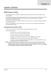
... Help part of the menu options to go to the Exit menu. • In any changes made and exit the BIOS Setup Utility. Follow these instructions: • To choose a menu, use the left and right arrow keys. • To choose an item, use the up and down arrow keys. • To...
... Help part of the menu options to go to the Exit menu. • In any changes made and exit the BIOS Setup Utility. Follow these instructions: • To choose a menu, use the left and right arrow keys. • To choose an item, use the up and down arrow keys. • To...
Service Guide
Page 36
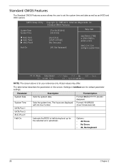
... parameters in boldface are displayed with 24-hour format. Format/Option Format MM/DD/YYYY (month/ day/year) Format: HH:MM:SS (hour:minute:second) Instructs the BIOS to configure system Date :Move Enter:Select - / + / Va:lu e F 1 0 : vSea E S C : E x i t F 1 : G e n earl H e l p F 9 : O p t i m i zeedf aDu l t s NOTE: The screen above is for the selected error parameter...
... parameters in boldface are displayed with 24-hour format. Format/Option Format MM/DD/YYYY (month/ day/year) Format: HH:MM:SS (hour:minute:second) Instructs the BIOS to configure system Date :Move Enter:Select - / + / Va:lu e F 1 0 : vSea E S C : E x i t F 1 : G e n earl H e l p F 9 : O p t i m i zeedf aDu l t s NOTE: The screen above is for the selected error parameter...

Service Guide
Page 46
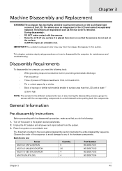
BIOS Flash Utilities The BIOS flash memory update is required for the following conditions: • New versions of system programs • New features or options • Restore BIOS when it becomes corrupted. This section contains instructions for the following BIOS utilities: • DOS flashit utility • WinPhlash utility • DMI Tools 36 Chapter 2
BIOS Flash Utilities The BIOS flash memory update is required for the following conditions: • New versions of system programs • New features or options • Restore BIOS when it becomes corrupted. This section contains instructions for the following BIOS utilities: • DOS flashit utility • WinPhlash utility • DMI Tools 36 Chapter 2
Service Guide
Page 50
... the succeeding disassembly section illustrates the entire disassembly sequence. During disassembly: • DO NOT make sure that you need the following : 1. General Information Pre-disassembly Instructions Before proceeding with the disassembly procedure, make contact with the corresponding components to the system and all power and signal cables from the images that...
... the succeeding disassembly section illustrates the entire disassembly sequence. During disassembly: • DO NOT make sure that you need the following : 1. General Information Pre-disassembly Instructions Before proceeding with the disassembly procedure, make contact with the corresponding components to the system and all power and signal cables from the images that...
Service Guide
Page 54
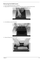
Apply pressure to one end of the device. 4. Removing the RAM Covers 1. Chapter 3 44 Lift the RAM Cover clear of the RAM Cover, while pulling up with both hands. See "Pre-disassembly Instructions" on page 40. 2. Grasp the Hinge Cover with the opposite hand as shown. 3.
Apply pressure to one end of the device. 4. Removing the RAM Covers 1. Chapter 3 44 Lift the RAM Cover clear of the RAM Cover, while pulling up with both hands. See "Pre-disassembly Instructions" on page 40. 2. Grasp the Hinge Cover with the opposite hand as shown. 3.
Service Guide
Page 104
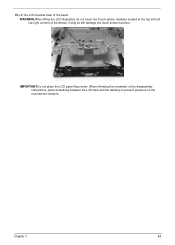
IMPORTANT:Do not place the LCD panel face down. Doing so will damage the touch screen function. WARNING:When lifting the LCD Assembly, do not touch the Touch sensor modules located at the top left and top right corners of the disassembly instructions, place something between the LCD face and the tabletop to prevent pressure on the touchscreen sensors. When following the remainder of the device. Chapter 3 94 Lift the LCD bracket clear of the bezel. 15.
IMPORTANT:Do not place the LCD panel face down. Doing so will damage the touch screen function. WARNING:When lifting the LCD Assembly, do not touch the Touch sensor modules located at the top left and top right corners of the disassembly instructions, place something between the LCD face and the tabletop to prevent pressure on the touchscreen sensors. When following the remainder of the device. Chapter 3 94 Lift the LCD bracket clear of the bezel. 15.
Service Guide
Page 173
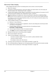
... reduce display brightness. If extensive pixel damage is present (different colored spots in the same locations on page 192. 10. See the User Manual for instructions on page 42. 5. Minimize or close all Windows. c. Click Apply and check the display. Remove and reinstall the video driver. 8. See "Disassembly Process" on page...
... reduce display brightness. If extensive pixel damage is present (different colored spots in the same locations on page 192. 10. See the User Manual for instructions on page 42. 5. Minimize or close all Windows. c. Click Apply and check the display. Remove and reinstall the video driver. 8. See "Disassembly Process" on page...

