
Service Guide
Page 8
Table of Contents Removing the Thermal Module 81 Removing the Fans 82 Removing the CPU 84 Removing the Mainboard 85 Removing the Frame 89 Removing the LCD Panel 95 Removing the Bluetooth Module 97 Removing the ... Bluetooth Module 110 Replacing the LCD Panel in the Frame 111 Replacing the Frame 113 Replacing the Mainboard 117 Replacing the CPU 120 Replacing the Fans 121 Replacing the Thermal Module 123 Replacing the WLAN Module 124 Replacing the TV Tuner Module 125 Replacing the Camera Module 126 Replacing the Power...
Table of Contents Removing the Thermal Module 81 Removing the Fans 82 Removing the CPU 84 Removing the Mainboard 85 Removing the Frame 89 Removing the LCD Panel 95 Removing the Bluetooth Module 97 Removing the ... Bluetooth Module 110 Replacing the LCD Panel in the Frame 111 Replacing the Frame 113 Replacing the Mainboard 117 Replacing the CPU 120 Replacing the Fans 121 Replacing the Thermal Module 123 Replacing the WLAN Module 124 Replacing the TV Tuner Module 125 Replacing the Camera Module 126 Replacing the Power...
Service Guide
Page 16
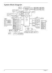
... 2.0 LPC PCIE 2 USB 10 Mini PCIE1 WLAN CNN 802.11 b/g/n 3G/WiMax PCIE 3 USB 12 Mini PCIE2 TV Tuner CARD CNN B-CAS CNN RTC Battery Fan CNN Reset Circuit Brightness Control LED Indicator REAR USB x4 USB 0,9,11,13 AUDIO AMP MAX9736BETJ+ QFN32 AUDIO CODEC ALC888S-VC2 LQFP48 5.1 Channel Azailia INT... SPK CNN (3) Head Phone & MIC IN CONN 5.1 Channel Line Line Line Line In Out(1) Out(1) Out(1) EC/KBC ITE8512 LQFP128 32.768KHz FAN CTRL 1Mb SPI (CPU/MXM) FLASH ROM IR IR RECEIVER Blaster System Ambient Light Sensor MAIN SW CNN 14.318MHz 6 Chapter 1
... 2.0 LPC PCIE 2 USB 10 Mini PCIE1 WLAN CNN 802.11 b/g/n 3G/WiMax PCIE 3 USB 12 Mini PCIE2 TV Tuner CARD CNN B-CAS CNN RTC Battery Fan CNN Reset Circuit Brightness Control LED Indicator REAR USB x4 USB 0,9,11,13 AUDIO AMP MAX9736BETJ+ QFN32 AUDIO CODEC ALC888S-VC2 LQFP48 5.1 Channel Azailia INT... SPK CNN (3) Head Phone & MIC IN CONN 5.1 Channel Line Line Line Line In Out(1) Out(1) Out(1) EC/KBC ITE8512 LQFP128 32.768KHz FAN CTRL 1Mb SPI (CPU/MXM) FLASH ROM IR IR RECEIVER Blaster System Ambient Light Sensor MAIN SW CNN 14.318MHz 6 Chapter 1
Service Guide
Page 41
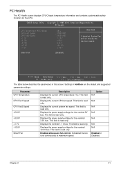
... : 48°C : 2095 RPM : 2103 RPM : 1.15 V : 1.09 V : 5.05 V : 12.12 V : 1.45 V Help Item If disabled, System Fan will run direstly the maximum speed. Parameter CPU Temperature CPU Fan1 Speed CPU Fan2 Speed +5.00V +3.30V +1.1V +12.0V Smart.... PC Health The PC Health screen displays CPU/Chipset temperature information and contains customizable safety monitors for the nominal 3.3V bus. CMOS Setup Utility - Smart Fan [Enabled] :Move Enter:Select - / + / Va:lu e F 1 0 : vSea E S C : E x i t F 1 : G e n earl H e l p F 9 : O p t i m i zeedf aDu l t s The table below describes ...
... : 48°C : 2095 RPM : 2103 RPM : 1.15 V : 1.09 V : 5.05 V : 12.12 V : 1.45 V Help Item If disabled, System Fan will run direstly the maximum speed. Parameter CPU Temperature CPU Fan1 Speed CPU Fan2 Speed +5.00V +3.30V +1.1V +12.0V Smart.... PC Health The PC Health screen displays CPU/Chipset temperature information and contains customizable safety monitors for the nominal 3.3V bus. CMOS Setup Utility - Smart Fan [Enabled] :Move Enter:Select - / + / Va:lu e F 1 0 : vSea E S C : E x i t F 1 : G e n earl H e l p F 9 : O p t i m i zeedf aDu l t s The table below describes ...
Service Guide
Page 52
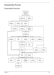
... Remove HDD Module Remove Audio Board Remove Rear Cover Remove Inverter Board Remove ODD Module Remove Touchscreen Board Remove Mainboard Shield Remove WLAN Board Remove FAN Remove VGA Board Remove TV Module Remove DIMM Module Remove Thermal Module Remove CPU Remove Mainboard Remove USB Board Remove IR Receiver Remove Frame Remove...
... Remove HDD Module Remove Audio Board Remove Rear Cover Remove Inverter Board Remove ODD Module Remove Touchscreen Board Remove Mainboard Shield Remove WLAN Board Remove FAN Remove VGA Board Remove TV Module Remove DIMM Module Remove Thermal Module Remove CPU Remove Mainboard Remove USB Board Remove IR Receiver Remove Frame Remove...
Service Guide
Page 53
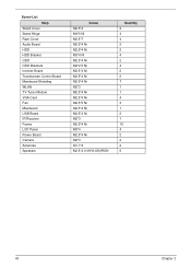
Screw List Step Stand Cover Stand Hinge Rear Cover Audio Board HDD HDD Bracket ODD ODD Brackets Inverter Board Touchscreen Control Board Mainboard Shielding WLAN TV Tuner Module VGA Card Fan Mainboard USB Board IR Receiver Frame LCD Panel Power Board Camera Antennas Speakers Screw M2.5*4 M4*6 Ni M2.5*7 M2.5*4 Ni M2.5*4 Ni M3*4 Ni M2.5*4 Ni M2*2.5 Ni M2.5*4 Ni M2.5*4 Ni M2.5*4 Ni M2*3 M2.5*4 Ni M2.5*4 Ni M2.5*5 Ni M2.5*4 Ni M2.5*4 Ni M2*3 M2.5*4 Ni M3*4 M2.5*4 Ni M2*3 M1.7*4 M2.5*4.0-I(NYLOK)IRON Quantity 2 4 4 2 2 4 2 4 2 2 7 1 1 4 3 1 2 1 15 4 2 2 2 6 43 Chapter 3
Screw List Step Stand Cover Stand Hinge Rear Cover Audio Board HDD HDD Bracket ODD ODD Brackets Inverter Board Touchscreen Control Board Mainboard Shielding WLAN TV Tuner Module VGA Card Fan Mainboard USB Board IR Receiver Frame LCD Panel Power Board Camera Antennas Speakers Screw M2.5*4 M4*6 Ni M2.5*7 M2.5*4 Ni M2.5*4 Ni M3*4 Ni M2.5*4 Ni M2*2.5 Ni M2.5*4 Ni M2.5*4 Ni M2.5*4 Ni M2*3 M2.5*4 Ni M2.5*4 Ni M2.5*5 Ni M2.5*4 Ni M2.5*4 Ni M2*3 M2.5*4 Ni M3*4 M2.5*4 Ni M2*3 M1.7*4 M2.5*4.0-I(NYLOK)IRON Quantity 2 4 4 2 2 4 2 4 2 2 7 1 1 4 3 1 2 1 15 4 2 2 2 6 43 Chapter 3

Service Guide
Page 91
Lift the thermal module away. 3 2 s 81 Chapter 3 See "Removing the Thermal Module" on page 81. 2. Loosen the four (4) captive screws in numerical order (1, 2, 3, then 4). 1 4 4. Disconnect the two (2) fan cables. 3. Removing the Thermal Module 1.
Lift the thermal module away. 3 2 s 81 Chapter 3 See "Removing the Thermal Module" on page 81. 2. Loosen the four (4) captive screws in numerical order (1, 2, 3, then 4). 1 4 4. Disconnect the two (2) fan cables. 3. Removing the Thermal Module 1.
Service Guide
Page 92
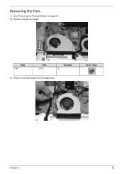
Step Fan Size 2.5*5 Quantity 2 3. See "Removing the Thermal Module" on page 81. 2. Screw Type Chapter 3 82 Remove the LVDS cable from the cable clips. Remove the two (2) screws. Removing the Fans 1.
Step Fan Size 2.5*5 Quantity 2 3. See "Removing the Thermal Module" on page 81. 2. Screw Type Chapter 3 82 Remove the LVDS cable from the cable clips. Remove the two (2) screws. Removing the Fans 1.
Service Guide
Page 93
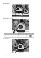
Remove the fan. Size 2.5*5 Quantity 2 Screw Type 83 Chapter 3 4. Remove the two (2) screws. Remove the fan. 5. Step Fan 6.
Remove the fan. Size 2.5*5 Quantity 2 Screw Type 83 Chapter 3 4. Remove the two (2) screws. Remove the fan. 5. Step Fan 6.

Service Guide
Page 131
Replacing the Fans 3. Step Fan Size 2.5*5 5. Quantity 2 Screw Type 121 Chapter 3 Replace the two (2) screws. Replace the left fan. Replace the right fan. 4.
Replacing the Fans 3. Step Fan Size 2.5*5 5. Quantity 2 Screw Type 121 Chapter 3 Replace the two (2) screws. Replace the left fan. Replace the right fan. 4.

Service Guide
Page 132
Step Fan Size 2.5*5 Quantity 2 Screw Type Chapter 3 122 Replace the two (2) screws. 6. Place the LVDS cable into the cable clips. 7.
Step Fan Size 2.5*5 Quantity 2 Screw Type Chapter 3 122 Replace the two (2) screws. 6. Place the LVDS cable into the cable clips. 7.

Service Guide
Page 133
Place the thermal module on to the mainboard. 2. Tighten the four (4) captive screws in reverse numerical order (4, 3, 2, then 1). 1 4 3 2 3. Connect the two (2) fan cables. 123 Chapter 3 Replacing the Thermal Module 1.
Place the thermal module on to the mainboard. 2. Tighten the four (4) captive screws in reverse numerical order (4, 3, 2, then 1). 1 4 3 2 3. Connect the two (2) fan cables. 123 Chapter 3 Replacing the Thermal Module 1.
Service Guide
Page 172
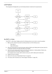
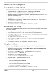
... 10 seconds. Remove the drives (see "Online Support Information" on page 42). 6. LCD Failure If the integrated LCD display fails, use the following occurs: • Fans start up • Status LEDs light up 2. Reseat the memory modules. 5. Restart the computer. Make sure the computer has power by checking at a time to...
... 10 seconds. Remove the drives (see "Online Support Information" on page 42). 6. LCD Failure If the integrated LCD display fails, use the following occurs: • Fans start up • Status LEDs light up 2. Reseat the memory modules. 5. Restart the computer. Make sure the computer has power by checking at a time to...
Service Guide
Page 174
... the computer is properly connected to correct the problem. 1. Replace the Motherboard. 6. Disconnect the power and open the casing to check the Thermal Unit and fan airways are still lost, replace the cables. 4. If the Issue is more than one at a time to the computer and the electrical outlet. 2. Right-click...
... the computer is properly connected to correct the problem. 1. Replace the Motherboard. 6. Disconnect the power and open the casing to check the Thermal Unit and fan airways are still lost, replace the cables. 4. If the Issue is more than one at a time to the computer and the electrical outlet. 2. Right-click...
Service Guide
Page 185
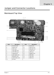
Jumper and Connector Locations Mainboard Top View 34 Chapter 5 19 2 1 5 6 18 17 7 16 8 15 Item 1 2 3 4 5 6 7 8 9 10 9 10 Description Iinverter conn power conn LCD conn GPU FAN conn CPU FAN conn camera conn card reader conn Bluetooth conn Home button conn IR conn Item 11 12 13 14 15 16 17 18 19 11 12 13 14 Description Audio conn light foot conn light pipe conn B-CAS conn USB conn Speaker conn PSU SYS PSU CPU SSD conn Chapter 5 175
Jumper and Connector Locations Mainboard Top View 34 Chapter 5 19 2 1 5 6 18 17 7 16 8 15 Item 1 2 3 4 5 6 7 8 9 10 9 10 Description Iinverter conn power conn LCD conn GPU FAN conn CPU FAN conn camera conn card reader conn Bluetooth conn Home button conn IR conn Item 11 12 13 14 15 16 17 18 19 11 12 13 14 Description Audio conn light foot conn light pipe conn B-CAS conn USB conn Speaker conn PSU SYS PSU CPU SSD conn Chapter 5 175
Service Guide
Page 193
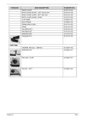
UMA/DIS HEATSINK DIS FAN UMA - CATEGORY ACER DESCRIPTION HINGE COVER REAR COVER SILVER - LEFT W/B CAS REAR COVER SILVER - LEFT ACER PART NO. 42.SCY07.002 60.SCY07.004 60.SCY07.005 60.SCY07.006 33.SDB07.001 33.SDB07.002 33.SCY07.003 60.SCY07.007 33.SCY07.004 33.SCY07.005 33.SCY07.006 23.SCY07.005 60.SDB07.006 60.SDB07.007 23.SDB07.001 23.SDB07.002 Chapter 6 183 LEFT W/O B-CAS REAR COVER SILVER - RIGHT LCD FRAME BACK FRAME FRAME RAM COVER HINGE ODD BRACKET HDD BRACKET MXM BRACKET SPEAKER SET HEAT SINK THERMAL MODULE - RIGHT FAN DIS -
UMA/DIS HEATSINK DIS FAN UMA - CATEGORY ACER DESCRIPTION HINGE COVER REAR COVER SILVER - LEFT W/B CAS REAR COVER SILVER - LEFT ACER PART NO. 42.SCY07.002 60.SCY07.004 60.SCY07.005 60.SCY07.006 33.SDB07.001 33.SDB07.002 33.SCY07.003 60.SCY07.007 33.SCY07.004 33.SCY07.005 33.SCY07.006 23.SCY07.005 60.SDB07.006 60.SDB07.007 23.SDB07.001 23.SDB07.002 Chapter 6 183 LEFT W/O B-CAS REAR COVER SILVER - RIGHT LCD FRAME BACK FRAME FRAME RAM COVER HINGE ODD BRACKET HDD BRACKET MXM BRACKET SPEAKER SET HEAT SINK THERMAL MODULE - RIGHT FAN DIS -


