
English Manual
Page 1
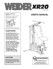
.... TO AVOID UNNECESSARY DELAYS, PLEASE CALL DIRECT TO OUR TOLL-FREE CUSTOMER HOT LINE. MST CAUTION Read all precautions and instructions in the space above for future reference. ª Patent Pending USER'S MANUAL Visit our website at www.weiderfitness.com new products, prizes, fitness tips, and much more! Model No. The trained technicians on our customer hot line will...
.... TO AVOID UNNECESSARY DELAYS, PLEASE CALL DIRECT TO OUR TOLL-FREE CUSTOMER HOT LINE. MST CAUTION Read all precautions and instructions in the space above for future reference. ª Patent Pending USER'S MANUAL Visit our website at www.weiderfitness.com new products, prizes, fitness tips, and much more! Model No. The trained technicians on our customer hot line will...
English Manual
Page 2
.... Remove the PART IDENTIFICATION CHART and the PART LIST/EXPLODED DRAWING before beginning assembly. Accordingly, the above limitation may not apply to products used as store display models. Some states do not allow limitations on how long an implied warranty lasts. TABLE OF CONTENTS LIMITED WARRANTY 2 IMPORTANT PRECAUTIONS 3 BEFORE YOU BEGIN 4 ASSEMBLY 5 ADJUSTMENT 17 TROUBLE-SHOOTING AND MAINTENANCE 20 CABLE DIAGRAM 21 ORDERING REPLACEMENT PARTS Back Cover Note: A PART IDENTIFICATION CHART and a PART LIST/EXPLODED DRAWING are attached...
.... Remove the PART IDENTIFICATION CHART and the PART LIST/EXPLODED DRAWING before beginning assembly. Accordingly, the above limitation may not apply to products used as store display models. Some states do not allow limitations on how long an implied warranty lasts. TABLE OF CONTENTS LIMITED WARRANTY 2 IMPORTANT PRECAUTIONS 3 BEFORE YOU BEGIN 4 ASSEMBLY 5 ADJUSTMENT 17 TROUBLE-SHOOTING AND MAINTENANCE 20 CABLE DIAGRAM 21 ORDERING REPLACEMENT PARTS Back Cover Note: A PART IDENTIFICATION CHART and a PART LIST/EXPLODED DRAWING are attached...
English Manual
Page 3
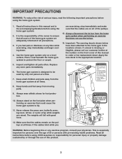
... the home gym system when performing an exercise that does not use of the pulleys. 13. Always wear athletic shoes for persons over the age of this product. 3 Never release the press arm, butterfly arms, leg lever, lat bar, or nylon strap while weights are on all times. Make sure that all users of the home gym system are adequately informed of all instructions in this or any exercise program...
... the home gym system when performing an exercise that does not use of the pulleys. 13. Always wear athletic shoes for persons over the age of this product. 3 Never release the press arm, butterfly arms, leg lever, lat bar, or nylon strap while weights are on all times. Make sure that all users of the home gym system are adequately informed of all instructions in this or any exercise program...
English Manual
Page 4
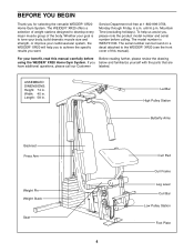
.... Lat Bar High Pulley Station Butterfly Arms Backrest Press Arm Weight Pin Weight Stack Seat Curl Pad Curl Frame Leg Lever Curl Bar Low Pulley Station Foot Plate 4 The WEIDER¨ XR20 offers a selection of weight stations designed to develop every major muscle group of this manual carefully before calling. Service Department toll-free at 1-800-999-3756, Monday through Friday, 6 a.m. To help you , please note the product model number and serial number...
.... Lat Bar High Pulley Station Butterfly Arms Backrest Press Arm Weight Pin Weight Stack Seat Curl Pad Curl Frame Leg Lever Curl Bar Low Pulley Station Foot Plate 4 The WEIDER¨ XR20 offers a selection of weight stations designed to develop every major muscle group of this manual carefully before calling. Service Department toll-free at 1-800-999-3756, Monday through Friday, 6 a.m. To help you , please note the product model number and serial number...
English Manual
Page 5
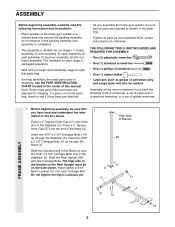
... the Stabilizer (5). Hand tighten a 5/16Ó Nylon Locknut (3) onto each end of this manual. Assembly will also be on the Rear Upright must be needed. Slide the Rear Upright (56) onto the Carriage Bolts. The hardware for shipping. Press a 2Ó Square Outer Cap (51) onto each Carriage Bolt. Press a 2Ó Square Inner Cap (27) into six stages: 1) frame assembly, 2) arm assembly, 3) cable assembly, 4) seat assembly, 5) leg lever assembly, and 6) curl frame...
... the Stabilizer (5). Hand tighten a 5/16Ó Nylon Locknut (3) onto each end of this manual. Assembly will also be on the Rear Upright must be needed. Slide the Rear Upright (56) onto the Carriage Bolts. The hardware for shipping. Press a 2Ó Square Outer Cap (51) onto each Carriage Bolt. Press a 2Ó Square Inner Cap (27) into six stages: 1) frame assembly, 2) arm assembly, 3) cable assembly, 4) seat assembly, 5) leg lever assembly, and 6) curl frame...
English Manual
Page 6
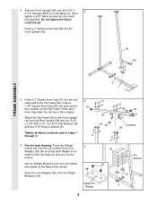
... that the large pin groove is ori- Press a 1 3/4Ó Square Inner Cap (44) into the top of the crossbar on the Top Frame. FRAME ASSEMBLY 42 65 3 4 1 3. Slide the Front Upright (42) onto the 5/16Ó x 2 2 1/2Ó Carriage Bolts (1) in steps 1 through 3. 3 27 3 4. Attach the Top Frame (55) to the Front Upright (42) and the Rear Upright (56) with four...
... that the large pin groove is ori- Press a 1 3/4Ó Square Inner Cap (44) into the top of the crossbar on the Top Frame. FRAME ASSEMBLY 42 65 3 4 1 3. Slide the Front Upright (42) onto the 5/16Ó x 2 2 1/2Ó Carriage Bolts (1) in steps 1 through 3. 3 27 3 4. Attach the Top Frame (55) to the Front Upright (42) and the Rear Upright (56) with four...

English Manual
Page 9
.... Be sure that the end of the cables. Route the Long 12 Cable around a ÒVÓ-Pulley 13 (6). IMPORTANT: While assembling the cables, do not overtighten the bolts and nuts attaching the pulleys. Before beginning this manual to hold the Cable in place. 7 6 50 42 23 21 7 6 50 21 23 47 9 Locate the Long Cable (23). CABLE ASSEMBLY 11. Route the Long Cable (23) around a ÒVÓ...
.... Be sure that the end of the cables. Route the Long 12 Cable around a ÒVÓ-Pulley 13 (6). IMPORTANT: While assembling the cables, do not overtighten the bolts and nuts attaching the pulleys. Before beginning this manual to hold the Cable in place. 7 6 50 42 23 21 7 6 50 21 23 47 9 Locate the Long Cable (23). CABLE ASSEMBLY 11. Route the Long Cable (23) around a ÒVÓ...

English Manual
Page 10
Route the Long Cable (23) around the 3 1/2Ó Pulley (15) attached to the Pulley Bracket (20). Wrap the Long Cable (23) around a 3 1/2Ó Pulley (15). Using a 5/16Ó x 5Ó Bolt (68) and a 5/16Ó Nylon Locknut (3), attach the Pulley Bracket (20) to the indicated hole in the direction shown. Route the Long Cable (23) around a ÒVÓ- 15 Pulley (6). Attach the Pulley (15) and a Cable Trap (66) to the...
Route the Long Cable (23) around the 3 1/2Ó Pulley (15) attached to the Pulley Bracket (20). Wrap the Long Cable (23) around a 3 1/2Ó Pulley (15). Using a 5/16Ó x 5Ó Bolt (68) and a 5/16Ó Nylon Locknut (3), attach the Pulley Bracket (20) to the indicated hole in the direction shown. Route the Long Cable (23) around a ÒVÓ- 15 Pulley (6). Attach the Pulley (15) and a Cable Trap (66) to the...

English Manual
Page 11
... (21), secure a 3 1/2Ó Pulley (15) and a Cable Trap (66) to the Press Frame as shown. CABLE ASSEMBLY 19. Hold a 3 1/2Ó Pulley (15) inside the indicated bracket on the Press Frame (17). Using a 3/8Ó x 8Ó Bolt (59), two 3/8Ó Flat Washers (9), and a 3/8Ó Nylon Locknut (21), attach the Pulley to the upper hole in the Front Upright (42) from the direction shown. Insert the...
... (21), secure a 3 1/2Ó Pulley (15) and a Cable Trap (66) to the Press Frame as shown. CABLE ASSEMBLY 19. Hold a 3 1/2Ó Pulley (15) inside the indicated bracket on the Press Frame (17). Using a 3/8Ó x 8Ó Bolt (59), two 3/8Ó Flat Washers (9), and a 3/8Ó Nylon Locknut (21), attach the Pulley to the upper hole in the Front Upright (42) from the direction shown. Insert the...

English Manual
Page 12
...). CABLE ASSEMBLY 22. Be sure that the Cable Trap (66) is turned to the upper hole in place and that the Cable is routed around the Pulley as shown. Be sure that the Cable Trap (66) is turned to the lower hole in place and that the Cable is routed around the 23 3 1/2Ó Pulley (15) attached to hold the Cable in the Front Upright (42). Locate...
...). CABLE ASSEMBLY 22. Be sure that the Cable Trap (66) is turned to the upper hole in place and that the Cable is routed around the Pulley as shown. Be sure that the Cable Trap (66) is turned to the lower hole in place and that the Cable is routed around the 23 3 1/2Ó Pulley (15) attached to hold the Cable in the Front Upright (42). Locate...

English Manual
Page 13
...) with two 1/4Ó x 2 1/2Ó Screws (43) and 28 42 two 1/4Ó Flat Washers (10). 41 43 10 SEAT ASSEMBLY 13 Attach the Backrest (41) to create slack in the Long Cable (23) before beginning this step. Note: Lift the Top Weight (76) on the 27 weight stack in the inset drawing. 57 27. Tighten the 1/2Ó Plain Nut (81...
...) with two 1/4Ó x 2 1/2Ó Screws (43) and 28 42 two 1/4Ó Flat Washers (10). 41 43 10 SEAT ASSEMBLY 13 Attach the Backrest (41) to create slack in the Long Cable (23) before beginning this step. Note: Lift the Top Weight (76) on the 27 weight stack in the inset drawing. 57 27. Tighten the 1/2Ó Plain Nut (81...

English Manual
Page 14
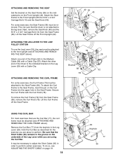
... Cable between the welded rod and the Leg Lever. Tighten a 5/16Ó Jam Nut (85) onto the Carriage Bolt. 32. Insert a 5/16Ó x 1 1/4Ó Carriage Bolt (72) through the lower hole in the Seat Frame (36). Rest the Seat Frame (36) on the indicated pin on the Front Upright (42). Attach the Seat Plate to the Front Upright with two 1/4Ó x 3/4Ó Screws (18). Attach...
... Cable between the welded rod and the Leg Lever. Tighten a 5/16Ó Jam Nut (85) onto the Carriage Bolt. 32. Insert a 5/16Ó x 1 1/4Ó Carriage Bolt (72) through the lower hole in the Seat Frame (36). Rest the Seat Frame (36) on the indicated pin on the Front Upright (42). Attach the Seat Plate to the Front Upright with two 1/4Ó x 3/4Ó Screws (18). Attach...

English Manual
Page 15
... x 1 1/4Ó Carriage Bolt (72) into each end of the keyhole. Orient the Short Cable (35) and the Curl Bar (77) as shown. Insert a 1 1/2Ó Square Inner Cap (32) into the keyhole in the Leg Lever (29). Secure the Curl Frame with two 1/4Ó x 3/4Ó Screws (18). Insert the other ...(28). This is firmly seated in the Seat Frame. See the right inset drawing. Attach the Curl Pad (80) to the Seat Frame (36) by inserting the pin on the Curl Frame into the Leg Lever (29). LEG LEVER ASSEMBLY 33. Press 3/4Ó Round Inner Caps (34) into the Seat Frame (36). Insert one ...
... x 1 1/4Ó Carriage Bolt (72) into each end of the keyhole. Orient the Short Cable (35) and the Curl Bar (77) as shown. Insert a 1 1/2Ó Square Inner Cap (32) into the keyhole in the Leg Lever (29). Secure the Curl Frame with two 1/4Ó x 3/4Ó Screws (18). Insert the other ...(28). This is firmly seated in the Seat Frame. See the right inset drawing. Attach the Curl Pad (80) to the Seat Frame (36) by inserting the pin on the Curl Frame into the Leg Lever (29). LEG LEVER ASSEMBLY 33. Press 3/4Ó Round Inner Caps (34) into the Seat Frame (36). Insert one ...

English Manual
Page 16
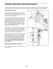
... cables does not move smoothly over the pulleys. 36. Before using the home gym system, pull each cable a few times to remove it by tightening the cables. See the CABLE DIAGRAM on page 20. 16 Make sure that the cables move smoothly, find and correct the problem. If there is used. If one of this manual. The use of this manual for proper cable routing. IMPORTANT: If the cables are not properly installed...
... cables does not move smoothly over the pulleys. 36. Before using the home gym system, pull each cable a few times to remove it by tightening the cables. See the CABLE DIAGRAM on page 20. 16 Make sure that the cables move smoothly, find and correct the problem. If there is used. If one of this manual. The use of this manual for proper cable routing. IMPORTANT: If the cables are not properly installed...
English Manual
Page 17
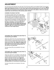
... weight station. 25 26 ATTACHING THE LAT BAR OR NYLON STRAP TO THE HIGH PULLEY STATION Attach the Lat Bar (54) to be attached between the Lat Bar and the Medium Cable with a Cable Clip (53). The Nylon Strap (39) can be attached in the correct starting position for the exercise to the Long Cable (23) with two Cable Clips. ADJUSTMENT The instructions below describe how each part of the home gym system can be set...
... weight station. 25 26 ATTACHING THE LAT BAR OR NYLON STRAP TO THE HIGH PULLEY STATION Attach the Lat Bar (54) to be attached between the Lat Bar and the Medium Cable with a Cable Clip (53). The Nylon Strap (39) can be attached in the correct starting position for the exercise to the Long Cable (23) with two Cable Clips. ADJUSTMENT The instructions below describe how each part of the home gym system can be set...
English Manual
Page 18
...; Carriage Bolt (14) and the Seat Knob (40). Lift the Curl Frame off the Front Upright (42). ATTACHING THE LEG LEVER TO THE LOW PULLEY STATION To use the Curl Bar (77), the curl frame must be necessary to adjust the Short Cable (35) in the Seat Frame. Attach the other end of the Leg Lever while you are using the Curl Bar. Remove the Curl Bar (77...
...; Carriage Bolt (14) and the Seat Knob (40). Lift the Curl Frame off the Front Upright (42). ATTACHING THE LEG LEVER TO THE LOW PULLEY STATION To use the Curl Bar (77), the curl frame must be necessary to adjust the Short Cable (35) in the Seat Frame. Attach the other end of the Leg Lever while you are using the Curl Bar. Remove the Curl Bar (77...
English Manual
Page 19
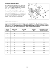
... WEIGHT RESISTANCE CHART This chart shows the approximate weight resistance at each exercise station. ÒTopÓ refers to one of the Curl Bar (77) can be changed by adjusting the Short Cable (35). To adjust the Short Cable, remove the 5/16Ó x 3/4Ó Bolt (73), 5/16Ó Flat Washer (8), and 5/16Ó Nylon Locknut (3). The butterfly arm resistance listed is in the correct starting position for each butterfly arm...
... WEIGHT RESISTANCE CHART This chart shows the approximate weight resistance at each exercise station. ÒTopÓ refers to one of the Curl Bar (77) can be changed by adjusting the Short Cable (35). To adjust the Short Cable, remove the 5/16Ó x 3/4Ó Bolt (73), 5/16Ó Flat Washer (8), and 5/16Ó Nylon Locknut (3). The butterfly arm resistance listed is in the correct starting position for each butterfly arm...
English Manual
Page 20
... in the cables before resistance is felt, 81 the cables should be removed by tightening the Long Cable (23) (see the back cover of the Long Cable further into the Weight Tube (63). Re-attach the Pulley and Cable Trap. If the cables need to be lifted off the weight stack. To do this manual. 20 Do not use the home gym system. The home gym system can be tightened. Next tighten the...
... in the cables before resistance is felt, 81 the cables should be removed by tightening the Long Cable (23) (see the back cover of the Long Cable further into the Weight Tube (63). Re-attach the Pulley and Cable Trap. If the cables need to be lifted off the weight stack. To do this manual. 20 Do not use the home gym system. The home gym system can be tightened. Next tighten the...
English Manual
Page 27
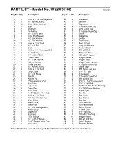
...; x 7/8Ó Plastic Bushing Top Weight Curl Bar Curl Knob Curl Frame Curl Pad 1/2Ó Plain Nut 1/2Ó Flat Washer Button Screw 1Ó Inner Cap 5/16Ó Jam Nut 1/2Ó x 3/4Ó Bushing Weight Insert 3/8Ó x 1 3/4Ó Bolt UserÕs Manual Exercise Poster Note: Ò#Ó indicates a non-illustrated part. PART LISTÑModel No. WESY01190 R0999A Key No. Qty. Description Key No. Specifications are subject to change without notice.
...; x 7/8Ó Plastic Bushing Top Weight Curl Bar Curl Knob Curl Frame Curl Pad 1/2Ó Plain Nut 1/2Ó Flat Washer Button Screw 1Ó Inner Cap 5/16Ó Jam Nut 1/2Ó x 3/4Ó Bushing Weight Insert 3/8Ó x 1 3/4Ó Bolt UserÕs Manual Exercise Poster Note: Ò#Ó indicates a non-illustrated part. PART LISTÑModel No. WESY01190 R0999A Key No. Qty. Description Key No. Specifications are subject to change without notice.
English Manual
Page 29
... (WESY01190) ¥ The NAME of the product (WEIDER¨ XR20 Home Gym System) ¥ The SERIAL NUMBER of the product (see the front cover of this manual) ¥ The KEY NUMBER and DESCRIPTION of the part(s) (see the PART LIST/EXPLODED DRAWING attached at 1-800-999-3756, Monday through Friday, 6 a.m. ORDERING REPLACEMENT PARTS To order replacement parts, simply call our Customer Service Department toll-free at the center of ICON Health & Fitness, Inc.
... (WESY01190) ¥ The NAME of the product (WEIDER¨ XR20 Home Gym System) ¥ The SERIAL NUMBER of the product (see the front cover of this manual) ¥ The KEY NUMBER and DESCRIPTION of the part(s) (see the PART LIST/EXPLODED DRAWING attached at 1-800-999-3756, Monday through Friday, 6 a.m. ORDERING REPLACEMENT PARTS To order replacement parts, simply call our Customer Service Department toll-free at the center of ICON Health & Fitness, Inc.


