
English Manual
Page 2
WEIDER is not responsible or liable for commercial or rental purposes, or products used for indirect, special or consequential damages arising out of or in connection .... TABLE OF CONTENTS LIMITED WARRANTY IMPORTANT PRECAUTIONS BEFORE YOU BEGIN ASSEMBLY HOW TO USE THE HOME GYM SYSTEM WEIGHT RESISTANCE CHART TROUBLE-SHOOTING AND MAINTENANCE CABLE DIAGRAMS ORDERING REPLACEMENT PARTS 2 3 4 5 24 26 27 29 Back Cover Note: A PART IDENTIFICATION CHART and a PART LIST/EXPLODED DRAWING are attached to the original purchaser...
WEIDER is not responsible or liable for commercial or rental purposes, or products used for indirect, special or consequential damages arising out of or in connection .... TABLE OF CONTENTS LIMITED WARRANTY IMPORTANT PRECAUTIONS BEFORE YOU BEGIN ASSEMBLY HOW TO USE THE HOME GYM SYSTEM WEIGHT RESISTANCE CHART TROUBLE-SHOOTING AND MAINTENANCE CABLE DIAGRAMS ORDERING REPLACEMENT PARTS 2 3 4 5 24 26 27 29 Back Cover Note: A PART IDENTIFICATION CHART and a PART LIST/EXPLODED DRAWING are attached to the original purchaser...
English Manual
Page 3
.... 5 Inspect and tighten`all users of the home gym system are raised. Always stand on a foot plate when performing an exercise that the cables remain on thepylleys at all of the pulleys. 14. If you are on all times. tary press arm. The assist arm can drop quickly...to ensure that does not use only. WARNING: Before beginning this or any commercial, rental, or institutional setting. Keep your physician. If the cables bind while'you feel pain or,dizziness at all instructions in any exercise program, consult your hands away from the leg press upright when the...
.... 5 Inspect and tighten`all users of the home gym system are raised. Always stand on a foot plate when performing an exercise that the cables remain on thepylleys at all of the pulleys. 14. If you are on all times. tary press arm. The assist arm can drop quickly...to ensure that does not use only. WARNING: Before beginning this or any commercial, rental, or institutional setting. Keep your physician. If the cables bind while'you feel pain or,dizziness at all instructions in any exercise program, consult your hands away from the leg press upright when the...
English Manual
Page 5
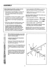
... will also be sure that you assemble them, unless instructed to do not dispose of the packing materials until you assemble the PRO 9655 be more convenient if you have been preattached for each stage is packaged separately. • Wait until assembly is completed. ...understand the infor- 1 mation in the box above. Press a 2" Square Inner Cap (27) into four stages: 1) frame assembly, 2) arm assembly, 3) cable and pulley assembly, and 4) seat and backrest assembly. THE FOLLOWING TOOLS (NOT INCLUDED) ARE REQUIRED FOR ASSEMBLY: • Two (2) adjustable wrenches 0 • ...
... will also be sure that you assemble them, unless instructed to do not dispose of the packing materials until you assemble the PRO 9655 be more convenient if you have been preattached for each stage is packaged separately. • Wait until assembly is completed. ...understand the infor- 1 mation in the box above. Press a 2" Square Inner Cap (27) into four stages: 1) frame assembly, 2) arm assembly, 3) cable and pulley assembly, and 4) seat and backrest assembly. THE FOLLOWING TOOLS (NOT INCLUDED) ARE REQUIRED FOR ASSEMBLY: • Two (2) adjustable wrenches 0 • ...
English Manual
Page 11
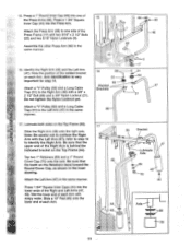
... Left Arm (47) in the same manner. 16. Wet the lower end of the Right and Left Arms (47, 48). Attach a "V"-Pulley (50) and a Long Cable Trap (31) to the Right Arm (48) with soapy water. Note: Be careful not to the Left Arm (47) in the inset drawing. Press a 1 3/4" Square... the indicated bracket on each Arm. 44 -/--- 45 55 Bracket 47 Lubricate Axle c' .69 45 44 Axle 69 70 11 - Attach a "V"-Pulley (50) and a Long Cable Trap (31) to confuse the Right Arm with two 5/16" x 2 1/2" Bolts (22) and two 5/16" Nylon Locknuts (3). Be sure that the upper end of the...
... Left Arm (47) in the same manner. 16. Wet the lower end of the Right and Left Arms (47, 48). Attach a "V"-Pulley (50) and a Long Cable Trap (31) to the Right Arm (48) with soapy water. Note: Be careful not to the Left Arm (47) in the inset drawing. Press a 1 3/4" Square... the indicated bracket on each Arm. 44 -/--- 45 55 Bracket 47 Lubricate Axle c' .69 45 44 Axle 69 70 11 - Attach a "V"-Pulley (50) and a Long Cable Trap (31) to confuse the Right Arm with two 5/16" x 2 1/2" Bolts (22) and two 5/16" Nylon Locknuts (3). Be sure that the upper end of the...
English Manual
Page 13
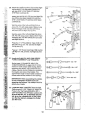
... the key number in the drawing. Before beginning this manual to the Assist Upright (74) with soapy water. Locate and open the parts bags labeled "CABLE ASSEMBLY" and "PULLEYS." The pulleys must be able to the Top Frame (55) with two 5/16" x 2 3/4" Bolts (11) and two 5/16" Nylon... Locknuts (3). Wrap the High Cable around a 3 1/2" Pulley (15). Slide a Short Foam Handgrip (80) onto the Left Dip Arm and onto the Right Dip Arm. Press two 1 1/4" Round Inner Caps...
... the key number in the drawing. Before beginning this manual to the Assist Upright (74) with soapy water. Locate and open the parts bags labeled "CABLE ASSEMBLY" and "PULLEYS." The pulleys must be able to the Top Frame (55) with two 5/16" x 2 3/4" Bolts (11) and two 5/16" Nylon... Locknuts (3). Wrap the High Cable around a 3 1/2" Pulley (15). Slide a Short Foam Handgrip (80) onto the Left Dip Arm and onto the Right Dip Arm. Press two 1 1/4" Round Inner Caps...
English Manual
Page 14
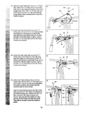
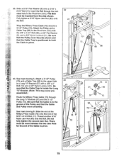
... (66) Is turned to the Top Frame (55) with a 3/8" x 2 1/2" Bolt (86) and a 3/8" Nylon Locknut (21). tioned to hold the Cable in the 58 groove of the "V"- that the Cable is in place. 24. Tighten the 3/8" x 2 1/2" Bolt (86) and the 3/8" Nylon Locknut (not shown). 58 31 86 50 48 26. See the inset.... Tighten the 3/8" x 2 1/2" Bolt (86) and the 3/8" Nylon Locknut (not shown). 31 58 50 Bracket 42 21 86 31 50 58 47 (1) 25. Route the High Cable (58) around the "V"Pulley (50) on the Right Arm (48). Be sure 25 W. Do not overtighten the Nylon Locknut; Route the High...
... (66) Is turned to the Top Frame (55) with a 3/8" x 2 1/2" Bolt (86) and a 3/8" Nylon Locknut (21). tioned to hold the Cable in the 58 groove of the "V"- that the Cable is in place. 24. Tighten the 3/8" x 2 1/2" Bolt (86) and the 3/8" Nylon Locknut (not shown). 58 31 86 50 48 26. See the inset.... Tighten the 3/8" x 2 1/2" Bolt (86) and the 3/8" Nylon Locknut (not shown). 31 58 50 Bracket 42 21 86 31 50 58 47 (1) 25. Route the High Cable (58) around the "V"Pulley (50) on the Right Arm (48). Be sure 25 W. Do not overtighten the Nylon Locknut; Route the High...

English Manual
Page 15
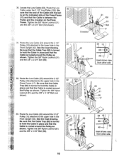
... is inside the Long "U"Bracket. Note: This assembly step shows how to complete the assembly of the Pulley and that the Cable is in the groove of the 3 1/2" Low Pulley (102) for part identification. The Bolt has been shown removed for shipping purposes. See the inset drawing. ... 3/8" Nylon Locknut (21) yet. Note: This may come pre-assembled. Attach the Pulley to the upper hole in the inset drawing. Be sure that the Cable and Pulley move smoothly. 27 66 21 57 28. 27. Remove the 3/8" Nylon Locknut (21), the Spacer, and the Pulley from the 3/8" x 3 3/4" Bolt (88...
... is inside the Long "U"Bracket. Note: This assembly step shows how to complete the assembly of the Pulley and that the Cable is in the groove of the 3 1/2" Low Pulley (102) for part identification. The Bolt has been shown removed for shipping purposes. See the inset drawing. ... 3/8" Nylon Locknut (21) yet. Note: This may come pre-assembled. Attach the Pulley to the upper hole in the inset drawing. Be sure that the Cable and Pulley move smoothly. 27 66 21 57 28. 27. Remove the 3/8" Nylon Locknut (21), the Spacer, and the Pulley from the 3/8" x 3 3/4" Bolt (88...
English Manual
Page 16
...and the 3/8" x 3 3/4" Bolt (not shown). 30 -;--- • 0 Crossbar 21 102 23 Ball 17 31. Be sure that the Cable Trap (66) is turned to hold the Cable in place and that the Cable is routed around the Pulley as shown. Tighten the 3/8" Nylon Locknut (21) and the 3/8" x 3 3/4" Bolt (88). 31 •... 88 66 42 Inset shows view from other side 32. See the inset drawing. 23 Be sure that the Cable Trap (66) is turned to hold the Cable in place and that the Cable is routed around the Pulley as shown. 30. Tighten the 3/8" Nylon -Locknut (21) ----,. 21 and the 3/8" x 3 3/4"...
...and the 3/8" x 3 3/4" Bolt (not shown). 30 -;--- • 0 Crossbar 21 102 23 Ball 17 31. Be sure that the Cable Trap (66) is turned to hold the Cable in place and that the Cable is routed around the Pulley as shown. Tighten the 3/8" Nylon Locknut (21) and the 3/8" x 3 3/4" Bolt (88). 31 •... 88 66 42 Inset shows view from other side 32. See the inset drawing. 23 Be sure that the Cable Trap (66) is turned to hold the Cable in place and that the Cable is routed around the Pulley as shown. 30. Tighten the 3/8" Nylon -Locknut (21) ----,. 21 and the 3/8" x 3 3/4"...

English Manual
Page 17
...of the Low Cable (23) to slide the Cable onto the Eyebolt. 58 71 24 ////L1_1/1/11.//h 36. Note: You may have to lift the Weight Cover (71) to the Long "U"-Bracket (57) with a 1/4" Nylon 34 Locknut (2) and a 1/4" Flat Washer (10). 34. Attach the end of the High Cable (58) ...onto the 35 3/8" x 4" Eyebolt (24). Locate the Military Press Cable (72). It should be threaded onto the end of the Cable so only a couple of the Military Press Cable onto 36 72 the other 3/8" x 4" Eyebolt (24). • 24 17 ...
...of the Low Cable (23) to slide the Cable onto the Eyebolt. 58 71 24 ////L1_1/1/11.//h 36. Note: You may have to lift the Weight Cover (71) to the Long "U"-Bracket (57) with a 1/4" Nylon 34 Locknut (2) and a 1/4" Flat Washer (10). 34. Attach the end of the High Cable (58) ...onto the 35 3/8" x 4" Eyebolt (24). Locate the Military Press Cable (72). It should be threaded onto the end of the Cable so only a couple of the Military Press Cable onto 36 72 the other 3/8" x 4" Eyebolt (24). • 24 17 ...
English Manual
Page 18
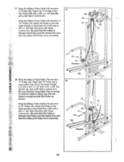
...55) with a 3/8" x 4 1/2" Bolt (112), a 3/8" Flat Washer (9), and a 3/8" Nylon Locknut (21). Attach the "V"-Pulley to hold the Cable in place and that the Cable and Pulley move smoothly. 55 50 21-a • 86 72 15 Bracket 2 • 38. Attach the Pulley to the Assist Upright (74) with ... on the Assist Arm (105) with a 3/8" x 1 3/4" Bolt (76) and a 3/8" Nylon Locknut (21). Wrap the Military Press Cable (72) around a "V"-Pulley (50). 37. Wrap the Military Press Cable (72) around a 3 1/2" Pulley (15). Attach the Pulley to the other bracket on the Assist Arm (105) with a 3/8" x...
...55) with a 3/8" x 4 1/2" Bolt (112), a 3/8" Flat Washer (9), and a 3/8" Nylon Locknut (21). Attach the "V"-Pulley to hold the Cable in place and that the Cable and Pulley move smoothly. 55 50 21-a • 86 72 15 Bracket 2 • 38. Attach the Pulley to the Assist Upright (74) with ... on the Assist Arm (105) with a 3/8" x 1 3/4" Bolt (76) and a 3/8" Nylon Locknut (21). Wrap the Military Press Cable (72) around a "V"-Pulley (50). 37. Wrap the Military Press Cable (72) around a 3 1/2" Pulley (15). Attach the Pulley to the other bracket on the Assist Arm (105) with a 3/8" x...
English Manual
Page 19
...and a 3/8" Nylon Locknut (21). There must be room between the two Jam Nuts for the end of the 5/16" x 2 3/4 Bolt (11). Attach the Pulley and a Cable Trap (66) to pivot. 40 9 15 57 72 15 A (0) 21 C 66 57 93 72 9 11 C 19 Insert the Bolt through the Long "U"-Bracket (57) ...and the 3 1/2" Pulley (15). See inset drawing B. Slide the end of the Military Press Cable (72) onto the end of the Cable to the Pivot Arm (101) with a 3/8" x 2" Bolt (12) and a 3/8" Nylon Locknut (21). Fully tighten a 5/16" Nylon Jam Nut (93) onto...
...and a 3/8" Nylon Locknut (21). There must be room between the two Jam Nuts for the end of the 5/16" x 2 3/4 Bolt (11). Attach the Pulley and a Cable Trap (66) to pivot. 40 9 15 57 72 15 A (0) 21 C 66 57 93 72 9 11 C 19 Insert the Bolt through the Long "U"-Bracket (57) ...and the 3 1/2" Pulley (15). See inset drawing B. Slide the end of the Military Press Cable (72) onto the end of the Cable to the Pivot Arm (101) with a 3/8" x 2" Bolt (12) and a 3/8" Nylon Locknut (21). Fully tighten a 5/16" Nylon Jam Nut (93) onto...
English Manual
Page 20
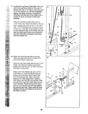
... the 3/8" x 3 3/4" Bolt (88), a 3/8" Flat Washer (9), and a 3/8" Nylon Locknut (21). Do not completely tighten the Nylon Locknut. The ball on the Cable must be threaded onto the end of the Cable only a couple of turns, as shown in the Rear Seat Frame (100) from the indicated side. (Note: The three holes are... for the end of the Bolt. Locate the Leg Press Cable (99). Insert the Bolt through the lowest hole in the inset drawing. 41. Attach the Pulley to the Leg Press Upright (56) with a 5/16" x 3"...
... the 3/8" x 3 3/4" Bolt (88), a 3/8" Flat Washer (9), and a 3/8" Nylon Locknut (21). Do not completely tighten the Nylon Locknut. The ball on the Cable must be threaded onto the end of the Cable only a couple of turns, as shown in the Rear Seat Frame (100) from the indicated side. (Note: The three holes are... for the end of the Bolt. Locate the Leg Press Cable (99). Insert the Bolt through the lowest hole in the inset drawing. 41. Attach the Pulley to the Leg Press Upright (56) with a 5/16" x 3"...
English Manual
Page 23
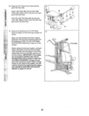
... of the Pad Tube. Slide a Foam Foam Pad (30) onto each end of the Pad Tube. 51. See the CABLE DIAGRAMS on pages 27 and 28. 36 30 34 28 34 30 0 29 0 PRO 9655 0 0 23 See TROUBLE-SHOOTING AND MAINTE- Insert a Pad Tube (28) into the Front Seat Frame (36). Ca rect... using the home gym system, pull each Pad Tube (28). If there is used. Make sure that the cables move smoothly, find and cor- NANCE on pages 29 and 30 of the cables does not move smoothly over the pulleys. Remove the backing from the PRO 9655 decal and apply it by tightening the...
... of the Pad Tube. Slide a Foam Foam Pad (30) onto each end of the Pad Tube. 51. See the CABLE DIAGRAMS on pages 27 and 28. 36 30 34 28 34 30 0 29 0 PRO 9655 0 0 23 See TROUBLE-SHOOTING AND MAINTE- Insert a Pad Tube (28) into the Front Seat Frame (36). Ca rect... using the home gym system, pull each Pad Tube (28). If there is used. Make sure that the cables move smoothly, find and cor- NANCE on pages 29 and 30 of the cables does not move smoothly over the pulleys. Remove the backing from the PRO 9655 decal and apply it by tightening the...
English Manual
Page 24
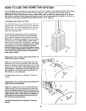
... RESISTANCE CHART on page 26 to find the approximate amount of resistance at each exercise station may vary from 10 pounds to the High Cable (58) with a Cable Clip (53). The Nylon Strap (39) can be attached in increments of 10 pounds. The weight setting of either weight stack, insert a...between the Lat Bar and the High Cable so the Lat Bar is in the correct starting position for the exercise to be reduced. The Nylon Strap (39) can be attached in the correct starting position for each exercise. CHANGING THE WEIGHT SETTING The PRO 9655 features two weight stacks. IMPORTANT: ...
... RESISTANCE CHART on page 26 to find the approximate amount of resistance at each exercise station may vary from 10 pounds to the High Cable (58) with a Cable Clip (53). The Nylon Strap (39) can be attached in increments of 10 pounds. The weight setting of either weight stack, insert a...between the Lat Bar and the High Cable so the Lat Bar is in the correct starting position for the exercise to be reduced. The Nylon Strap (39) can be attached in the correct starting position for each exercise. CHANGING THE WEIGHT SETTING The PRO 9655 features two weight stacks. IMPORTANT: ...
English Manual
Page 25
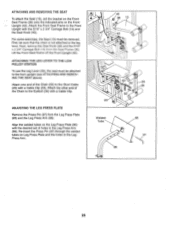
...ATTACHING AND REMOVING THE SEAT above). Align the welded tubes on the Leg Press Plate (95) with a Cable Clip. For some exercises, the Seat (13) must be sure that the chain is not attached to the... ATTACHING AND REMOVING THE SEAT To attach the Seat (13), set of the Chain (52) to the Short Cable (23) with the 5/16" x 2 3/4" Carriage Bolt (14) and the Seat Knob (40). Attach the other... end of the Chain to the Front Upright with a Cable Clip (53). Attach the Front Seat Frame to the Eyebolt (35) with the desired set the bracket on ...
...ATTACHING AND REMOVING THE SEAT above). Align the welded tubes on the Leg Press Plate (95) with a Cable Clip. For some exercises, the Seat (13) must be sure that the chain is not attached to the... ATTACHING AND REMOVING THE SEAT To attach the Seat (13), set of the Chain (52) to the Short Cable (23) with the 5/16" x 2 3/4" Carriage Bolt (14) and the Seat Knob (40). Attach the other... end of the Chain to the Front Upright with a Cable Clip (53). Attach the Front Seat Frame to the Eyebolt (35) with the desired set the bracket on ...

English Manual
Page 27
...1/2" Pulley (15) to be tightened. Thread the Eyebolt into the middle of the Long "U"-Brackets (57). Tighten the 1/4" Nylon Locknut (2) that the Cable and Pulley move smoothly. 66 0 15 21 0 57 0 The other hole in the same manner. Repeat until the 3/8" Nut touches the Weight Cover.... TROUBLE-SHOOTING AND MAINTENANCE Inspect and tighten all parts each time you use solvents. To tighten the cables, insert the weight pin into the Weight Cover (71) until there is first used on the 3/8" x 4" Eyebolt approximately three turns. ...
...1/2" Pulley (15) to be tightened. Thread the Eyebolt into the middle of the Long "U"-Brackets (57). Tighten the 1/4" Nylon Locknut (2) that the Cable and Pulley move smoothly. 66 0 15 21 0 57 0 The other hole in the same manner. Repeat until the 3/8" Nut touches the Weight Cover.... TROUBLE-SHOOTING AND MAINTENANCE Inspect and tighten all parts each time you use solvents. To tighten the cables, insert the weight pin into the Weight Cover (71) until there is first used on the 3/8" x 4" Eyebolt approximately three turns. ...
English Manual
Page 28
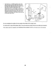
... o 11 8 99 0 93 -J 100 93--. Remove the 5/16" x 2 3/4" Bolt (11), the 5/16" Washer (8), the end of the Cable, and both 5/16" Nylon Jam Nuts (93) from the Rear Seat Frame. Do not overtighten the cables; the top weight will be moved to slip off the weight stack. If additional slack is felt... while using the Leg Press Arm (96), then the end of this manual. 28 Remove the cable and re-install it may have become twisted. If the cables need to be replaced, see ORDERING REPLACEMENT PARTS on the back cover of 3 the Leg Press...
... o 11 8 99 0 93 -J 100 93--. Remove the 5/16" x 2 3/4" Bolt (11), the 5/16" Washer (8), the end of the Cable, and both 5/16" Nylon Jam Nuts (93) from the Rear Seat Frame. Do not overtighten the cables; the top weight will be moved to slip off the weight stack. If additional slack is felt... while using the Leg Press Arm (96), then the end of this manual. 28 Remove the cable and re-install it may have become twisted. If the cables need to be replaced, see ORDERING REPLACEMENT PARTS on the back cover of 3 the Leg Press...
English Manual
Page 29
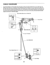
... pages show the proper positioning of the High Cable (58), the Low Cable (23), the Military Press Cable (72), and the Leg Press Cable (99). Be sure that the cable traps do not touch or bind the cables. If the cables have been assembled correctly. High Cable (58) and Low Cable (23) 7 5 2 3 4 6 High Cable (58) 5-Long "U"-Bracket 1 High Pulley Low...
... pages show the proper positioning of the High Cable (58), the Low Cable (23), the Military Press Cable (72), and the Leg Press Cable (99). Be sure that the cable traps do not touch or bind the cables. If the cables have been assembled correctly. High Cable (58) and Low Cable (23) 7 5 2 3 4 6 High Cable (58) 5-Long "U"-Bracket 1 High Pulley Low...

English Manual
Page 30
Military Press Cable (72) and Leg Press Cable (99) 2 Military Press Cable (72) 6 4 Rear Weight Stack-1 3 5 8-Pivot Arm 0 7 1-Long "U"-Bracket 3 2 0 4-Rear Seat Frame Leg Press Cable (99) 30
Military Press Cable (72) and Leg Press Cable (99) 2 Military Press Cable (72) 6 4 Rear Weight Stack-1 3 5 8-Pivot Arm 0 7 1-Long "U"-Bracket 3 2 0 4-Rear Seat Frame Leg Press Cable (99) 30
English Manual
Page 33
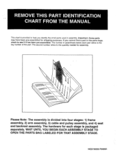
... OPEN THE PARTS BAG LABELED FOR THAT ASSEMBLY STAGE. The number in parenthesis below each stage is divided into four stages: 1) frame assembly, 2) arm assembly, 3) cable and pulley assembly, and 4) seat and backrest assembly.
... OPEN THE PARTS BAG LABELED FOR THAT ASSEMBLY STAGE. The number in parenthesis below each stage is divided into four stages: 1) frame assembly, 2) arm assembly, 3) cable and pulley assembly, and 4) seat and backrest assembly.


