
English Manual
Page 1
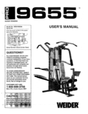
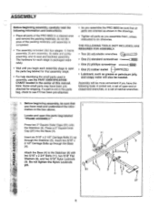
... UNNECESSARY DELAYS, PLEASE CALL DIRECT TO OUR TOLL-FREE CUSTOMER HOT LINE. mitted to you complete sat- isfaction through direct assis- MST CAUTI ,Read all oreceutiOna and instruc Cons inthis manual before using tbls equipmentSave s Minim for reference. 0 0 0 • 0 Serial Number Decal (Under Seat) USER'S MANUAL QUESTIONS? 0 a 9655 PATENT PENDING Model No. tance from our factory. The trained technicians on our customer hot...
... UNNECESSARY DELAYS, PLEASE CALL DIRECT TO OUR TOLL-FREE CUSTOMER HOT LINE. mitted to you complete sat- isfaction through direct assis- MST CAUTI ,Read all oreceutiOna and instruc Cons inthis manual before using tbls equipmentSave s Minim for reference. 0 0 0 • 0 Serial Number Decal (Under Seat) USER'S MANUAL QUESTIONS? 0 a 9655 PATENT PENDING Model No. tance from our factory. The trained technicians on our customer hot...
English Manual
Page 2
... LIMITED WARRANTY IMPORTANT PRECAUTIONS BEFORE YOU BEGIN ASSEMBLY HOW TO USE THE HOME GYM SYSTEM WEIGHT RESISTANCE CHART TROUBLE-SHOOTING AND MAINTENANCE CABLE DIAGRAMS ORDERING REPLACEMENT PARTS 2 3 4 5 24 26 27 29 Back Cover Note: A PART IDENTIFICATION CHART and a PART LIST/EXPLODED DRAWING are attached to freight damage, abuse, misuse, improper or abnormal usage or repairs not provided by an ICON authorized service center, products used for commercial or rental purposes, or products used as store display models. Remove the PART...
... LIMITED WARRANTY IMPORTANT PRECAUTIONS BEFORE YOU BEGIN ASSEMBLY HOW TO USE THE HOME GYM SYSTEM WEIGHT RESISTANCE CHART TROUBLE-SHOOTING AND MAINTENANCE CABLE DIAGRAMS ORDERING REPLACEMENT PARTS 2 3 4 5 24 26 27 29 Back Cover Note: A PART IDENTIFICATION CHART and a PART LIST/EXPLODED DRAWING are attached to freight damage, abuse, misuse, improper or abnormal usage or repairs not provided by an ICON authorized service center, products used for commercial or rental purposes, or products used as store display models. Remove the PART...
English Manual
Page 3
... being used . Keep your body weight IS Placed on all parts often Replace any commercial, rental, or institutional setting. Always disconnect the lat bar from moving parts. WARNING: Before beginning this product Pa' • 4k, ICON assumes no responsibility for persons over the age of this or any time while exercising, stop immediately and make sure,that the cables remain on the assist arm:. The home gym...
... being used . Keep your body weight IS Placed on all parts often Replace any commercial, rental, or institutional setting. Always disconnect the lat bar from moving parts. WARNING: Before beginning this product Pa' • 4k, ICON assumes no responsibility for persons over the age of this or any time while exercising, stop immediately and make sure,that the cables remain on the assist arm:. The home gym...
English Manual
Page 4
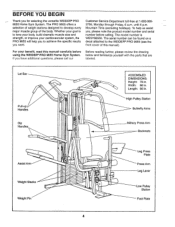
... PRO 9655 offers a selection of weight stations designed to the WEIDER® PRO 9655 (see the front cover of the body. Lat Bar Pull-up Handles Dip Handles Aveiro,. it* E-rift a • • O ASSEMBLED DIMENSIONS: Height: 78 in. BEFORE YOU BEGIN Thank you want. If you , please note the product model number and serial number before using the WEIDER® PRO 9655 Home Gym System. until 6 p.m. To help you to achieve the specific...
... PRO 9655 offers a selection of weight stations designed to the WEIDER® PRO 9655 (see the front cover of the body. Lat Bar Pull-up Handles Dip Handles Aveiro,. it* E-rift a • • O ASSEMBLED DIMENSIONS: Height: 78 in. BEFORE YOU BEGIN Thank you want. If you , please note the product model number and serial number before using the WEIDER® PRO 9655 Home Gym System. until 6 p.m. To help you to achieve the specific...
English Manual
Page 5
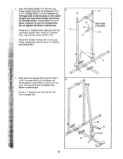
...: 1) frame assembly, 2) arm assembly, 3) cable and pulley assembly, and 4) seat and backrest assembly. Do not tighten the Nylon Locknuts yet. 51 1 3 4 27 Note: Some small parts may have read the following tools: A socket set, a set of open-end or closed-end wrenches, or a set of this manual. Locate and open the parts bag labeled for shipping. Insert two 5/16" x 8 5 2 1/2" Carriage Bolts up 51 through the Base (4). LL1 Attach the Base...
...: 1) frame assembly, 2) arm assembly, 3) cable and pulley assembly, and 4) seat and backrest assembly. Do not tighten the Nylon Locknuts yet. 51 1 3 4 27 Note: Some small parts may have read the following tools: A socket set, a set of open-end or closed-end wrenches, or a set of this manual. Locate and open the parts bag labeled for shipping. Insert two 5/16" x 8 5 2 1/2" Carriage Bolts up 51 through the Base (4). LL1 Attach the Base...
English Manual
Page 6
... Bolts. Attach the Rubber Bumper (91) to the Leg Press Upright (56) with the #8 x 1/2" Self-tapping Screw (87). 2 74 9-.27 27 87 91 ) 7r 27 High Sides of the brackets on the Assist Upright and Leg Press Upright should be on the side shown. Slide the Assist Upright (74) and the Leg Press Upright (56) onto the indicated 5/16" x 2 1/2" Carriage Bolts (1) in the Base (4). 3 Hand-tighten...
... Bolts. Attach the Rubber Bumper (91) to the Leg Press Upright (56) with the #8 x 1/2" Self-tapping Screw (87). 2 74 9-.27 27 87 91 ) 7r 27 High Sides of the brackets on the Assist Upright and Leg Press Upright should be on the side shown. Slide the Assist Upright (74) and the Leg Press Upright (56) onto the indicated 5/16" x 2 1/2" Carriage Bolts (1) in the Base (4). 3 Hand-tighten...
English Manual
Page 10
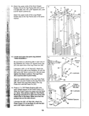
... Locate and open the parts bag labeled "ARM ASSEMBLY." 13 Be sure there is a Bushing (98) in each end of holes in the Leg Press Arm (96). Lubricate a 3/8" x 3 1/4" Bolt (67). The Leg Press Arm must be on the Press Frame (17). Make sure that the pulleys are on the Leg Press Plate (95) with one set of the indi- Attach the upper ends of the Stabilizer (5). Lubricate the 3/8" x 8" Bolt (59). Attach the Press...
... Locate and open the parts bag labeled "ARM ASSEMBLY." 13 Be sure there is a Bushing (98) in each end of holes in the Leg Press Arm (96). Lubricate a 3/8" x 3 1/4" Bolt (67). The Leg Press Arm must be on the Press Frame (17). Make sure that the pulleys are on the Leg Press Plate (95) with one set of the indi- Attach the upper ends of the Stabilizer (5). Lubricate the 3/8" x 8" Bolt (59). Attach the Press...
English Manual
Page 11
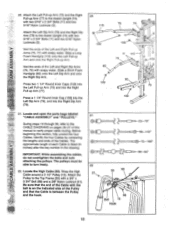
...Top Frame (55). Slide a 10" Pad (45) onto the lower end of the Right Arm is very important for step 14. Attach the Press Arm (46) to the Right Arm (48) with the Left Arm (47); Attach a "V"-Pulley (50) and a Long Cable Trap (31) to one of the welded bracket on the Top Frame... 47 Lubricate Axle c' .69 45 44 Axle 69 70 11 - Attach the Left Arm (47) in the inset drawing. Do not tighten the Nylon Locknut yet. Identify the Right Arm (48) and the Left Arm (47). refer to step 13 to confuse the Right Arm with a 3/8" x 2 1/2" Bolt (86) and a 3/8" Nylon Locknut (21). Press a ...
...Top Frame (55). Slide a 10" Pad (45) onto the lower end of the Right Arm is very important for step 14. Attach the Press Arm (46) to the Right Arm (48) with the Left Arm (47); Attach a "V"-Pulley (50) and a Long Cable Trap (31) to one of the welded bracket on the Top Frame... 47 Lubricate Axle c' .69 45 44 Axle 69 70 11 - Attach the Left Arm (47) in the inset drawing. Do not tighten the Nylon Locknut yet. Identify the Right Arm (48) and the Left Arm (47). refer to step 13 to confuse the Right Arm with a 3/8" x 2 1/2" Bolt (86) and a 3/8" Nylon Locknut (21). Press a ...
English Manual
Page 13
... the Cable is listed (in inches) after the key number in the drawing. Attach the Left Dip Arm (78) and the Right Dip Arm (79) to the Top Frame (55) with soapy water. Locate and open the parts bags labeled "CABLE ASSEMBLY" and "PULLEYS." During steps 19 through 39, refer to turn freely. ' 22. IMPORTANT: While assembling the cables, do not overtighten the bolts and nuts attaching the pulleys. Press a 1 1/4" Round...
... the Cable is listed (in inches) after the key number in the drawing. Attach the Left Dip Arm (78) and the Right Dip Arm (79) to the Top Frame (55) with soapy water. Locate and open the parts bags labeled "CABLE ASSEMBLY" and "PULLEYS." During steps 19 through 39, refer to turn freely. ' 22. IMPORTANT: While assembling the cables, do not overtighten the bolts and nuts attaching the pulleys. Press a 1 1/4" Round...
English Manual
Page 20
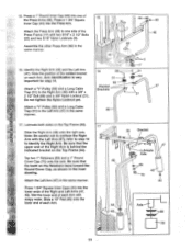
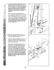
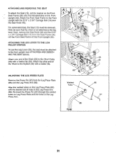
... Rear Seat Frame (100) from the indicated side. (Note: The three holes are for the end of the Pulley. Do not fully tighten the second Jam Nut. 41. Be sure that the Cable and Pulley move smoothly and that the Cable is between the two Jam Nuts for cable adjustment.) Tighten a 5/16" Nylon Jam Nut (93) onto the Bolt. Attach the Pulley to the Leg Press Arm...
... Rear Seat Frame (100) from the indicated side. (Note: The three holes are for the end of the Pulley. Do not fully tighten the second Jam Nut. 41. Be sure that the Cable and Pulley move smoothly and that the Cable is between the two Jam Nuts for cable adjustment.) Tighten a 5/16" Nylon Jam Nut (93) onto the Bolt. Attach the Pulley to the Leg Press Arm...

English Manual
Page 21
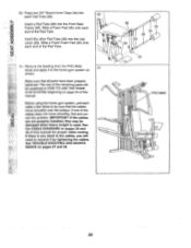
... (110) to the Leg Press Upright with a 1/4" Flat Washer (10) onto the Carriage Bolt. Attach the top of a Seat (13) to the Rear Backrest (85) with two 1/4" x 1/2" Screws 44 (18). Tighten a 1/4" Nylon Locknut (2) with a 1/4" x 2 1/2" Screw (43) and a 1/4" Flat Washer (10). 85 56 A 37 92 18 43 10 2 44. Attach one end of the Rear Backrest (85) to the Assist Arm (105) with a 1/4" Flat...
... (110) to the Leg Press Upright with a 1/4" Flat Washer (10) onto the Carriage Bolt. Attach the top of a Seat (13) to the Rear Backrest (85) with two 1/4" x 1/2" Screws 44 (18). Tighten a 1/4" Nylon Locknut (2) with a 1/4" x 2 1/2" Screw (43) and a 1/4" Flat Washer (10). 85 56 A 37 92 18 43 10 2 44. Attach one end of the Rear Backrest (85) to the Assist Arm (105) with a 1/4" Flat...
English Manual
Page 23
... to the home gym system as 51 shown. See the CABLE DIAGRAMS on pages 27 and 28. 36 30 34 28 34 30 0 29 0 PRO 9655 0 0 23 If one of this manual. Press two 3/4" Round Inner Caps (34) into the Front Seat Frame (36). Remove the backing from the PRO 9655 decal and apply it by tightening the cables. See TROUBLE-SHOOTING AND MAINTE- ASSEMBLY 50...
... to the home gym system as 51 shown. See the CABLE DIAGRAMS on pages 27 and 28. 36 30 34 28 34 30 0 29 0 PRO 9655 0 0 23 If one of this manual. Press two 3/4" Round Inner Caps (34) into the Front Seat Frame (36). Remove the backing from the PRO 9655 decal and apply it by tightening the cables. See TROUBLE-SHOOTING AND MAINTE- ASSEMBLY 50...
English Manual
Page 24
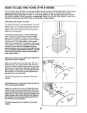
... the home gym system should be set up for the exercise to be adjusted. HOW TO USE THE HOME GYM SYSTEM The instructions below describe how each part of resistance at each weight station. 0 sN ATTACHING THE LAT BAR OR NYLON STRAP TO THE HIGH PULLEY STATION Attach the Lat Bar (54) to the High Cable (58) with a Cable Clip (53). To change the weight setting of either weight stack can be changed from the weight setting. 25 Use the WEIGHT RESISTANCE CHART...
... the home gym system should be set up for the exercise to be adjusted. HOW TO USE THE HOME GYM SYSTEM The instructions below describe how each part of resistance at each weight station. 0 sN ATTACHING THE LAT BAR OR NYLON STRAP TO THE HIGH PULLEY STATION Attach the Lat Bar (54) to the High Cable (58) with a Cable Clip (53). To change the weight setting of either weight stack can be changed from the weight setting. 25 Use the WEIGHT RESISTANCE CHART...
English Manual
Page 25
...), set of the Chain (52) to the Short Cable (23) with the 5/16" x 2 3/4" Carriage Bolt (14) and the Seat Knob (40). First, be sure that the chain is not attached to the Eyebolt (35) with a Cable Clip. ADJUSTING THE LEG PRESS PLATE Remove the Press Pin (97) from the Seat Frame (36). For some exercises, the Seat (13) must be removed. Attach one end of holes in the Leg Press Arm...
...), set of the Chain (52) to the Short Cable (23) with the 5/16" x 2 3/4" Carriage Bolt (14) and the Seat Knob (40). First, be sure that the chain is not attached to the Eyebolt (35) with a Cable Clip. ADJUSTING THE LEG PRESS PLATE Remove the Press Pin (97) from the Seat Frame (36). For some exercises, the Seat (13) must be removed. Attach one end of holes in the Leg Press Arm...

English Manual
Page 26
The other numbers refer to the 6 lb. weight plates. WEIGHT PLATES PRESS ARM (lbs.) BUTTERFLY ARM (lbs.) LEG LEVER (lbs.) HIGH PULLEY (lbs.) LOW PULLEY (lbs.) MILITARY PRESS ARM (lbs.) LEG PRESS (lbs.) ASSIST ARM (lbs.) Top 12 1 40 2 62 ,8 107 128 146 7 162 8 190 9 205 10 - 220 1 243 ... 176 292 1 305 207 335 249 375 262 412 275 458 310 26 top weight. The butterfly arm resistance listed is the resistance for each station. 'Top" refers to the 10 lb. WEIGHT RESISTANCE CHART This chart shows the approximate weight resistance at each butterfly...
The other numbers refer to the 6 lb. weight plates. WEIGHT PLATES PRESS ARM (lbs.) BUTTERFLY ARM (lbs.) LEG LEVER (lbs.) HIGH PULLEY (lbs.) LOW PULLEY (lbs.) MILITARY PRESS ARM (lbs.) LEG PRESS (lbs.) ASSIST ARM (lbs.) Top 12 1 40 2 62 ,8 107 128 146 7 162 8 190 9 205 10 - 220 1 243 ... 176 292 1 305 207 335 249 375 262 412 275 458 310 26 top weight. The butterfly arm resistance listed is the resistance for each station. 'Top" refers to the 10 lb. WEIGHT RESISTANCE CHART This chart shows the approximate weight resistance at each butterfly...

English Manual
Page 27
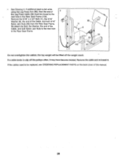
... the Cable Trap (66), Pulley, and Long "U"-Bracket. The home gym system can be tightened. Tighten the 1/4" Nylon Locknut (2) that the Cable Trap is first used on the 3/8" x 4" Eyebolt approximately three turns. Re-attach the Pulley and Cable Trap. Slide the High Cable back onto the Eyebolt. TROUBLE-SHOOTING AND MAINTENANCE Inspect and tighten all parts each time you use solvents. Replace any slack is felt when using the rear weight stack...
... the Cable Trap (66), Pulley, and Long "U"-Bracket. The home gym system can be tightened. Tighten the 1/4" Nylon Locknut (2) that the Cable Trap is first used on the 3/8" x 4" Eyebolt approximately three turns. Re-attach the Pulley and Cable Trap. Slide the High Cable back onto the Eyebolt. TROUBLE-SHOOTING AND MAINTENANCE Inspect and tighten all parts each time you use solvents. Replace any slack is felt when using the rear weight stack...
English Manual
Page 28
... next hole in the Rear Seat Frame. 96 o 11 8 99 0 93 -J 100 93--. Do not overtighten the cables; If the cables need to slip off the weight stack. If a cable tends to be lifted off the pulleys often, it . Remove the 5/16" x 2 3/4" Bolt (11), the 5/16" Washer (8), the end of this manual. 28 • See Drawing 3. Remove the cable and re-install it may have...
... next hole in the Rear Seat Frame. 96 o 11 8 99 0 93 -J 100 93--. Do not overtighten the cables; If the cables need to slip off the weight stack. If a cable tends to be lifted off the pulleys often, it . Remove the 5/16" x 2 3/4" Bolt (11), the 5/16" Washer (8), the end of this manual. 28 • See Drawing 3. Remove the cable and re-install it may have...
English Manual
Page 32
... Service Department toll-free at the center of this manual). 4. To help us assist you, please be prepared to give the following information: 1. until 6 p.m. The MODEL NUMBER of the product (WEIDER' PRO 9655 Home Gym System). 3. The SERIAL NUMBER of this manual). • Part No. 133900 R0996A Printed in Canada 1996 ICON Health & Fitness, Inc. The KEY NUMBER and DESCRIPTION of the part(s) (see the front cover of the product (see the PART LIST...
... Service Department toll-free at the center of this manual). 4. To help us assist you, please be prepared to give the following information: 1. until 6 p.m. The MODEL NUMBER of the product (WEIDER' PRO 9655 Home Gym System). 3. The SERIAL NUMBER of this manual). • Part No. 133900 R0996A Printed in Canada 1996 ICON Health & Fitness, Inc. The KEY NUMBER and DESCRIPTION of the part(s) (see the front cover of the product (see the PART LIST...
English Manual
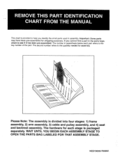
Page 33
... ASSEMBLY STAGE TO OPEN THE PARTS BAG LABELED FOR THAT ASSEMBLY STAGE. The hardware for each part refers to the key number of the part. Please Note: The assembly is divided into four stages: 1) frame assembly, 2) arm assembly, 3) cable and pulley assembly, and 4) seat and backrest assembly. If you identify the small parts used in assembly. REMOVE THIS PART IDENTIFICATION CHART FROM THE MANUAL This chart is provided to help'you cannot find a part in the parts...
... ASSEMBLY STAGE TO OPEN THE PARTS BAG LABELED FOR THAT ASSEMBLY STAGE. The hardware for each part refers to the key number of the part. Please Note: The assembly is divided into four stages: 1) frame assembly, 2) arm assembly, 3) cable and pulley assembly, and 4) seat and backrest assembly. If you identify the small parts used in assembly. REMOVE THIS PART IDENTIFICATION CHART FROM THE MANUAL This chart is provided to help'you cannot find a part in the parts...
English Manual
Page 40
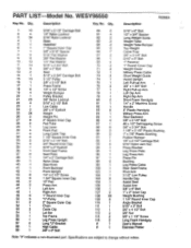
... 1" x 7/8" Plastic Bushing Rubber Bumper 1/4" x 2 1/2" Carriage Bolt 5/16" Nylon Jam Nut Press Bracket Leg Press Plate Leg Press Arm Press Pin Bushing Leg Press Cable Rear Seat Frame Pivot Arm 3 1/2" Low Pulley Handle Cap Assist Seat Assist Arm 3/8" x 6" Bolt 1" x 2" Inner Cap Weight Bushing 1 1/4" Round Inner Cap Angle Bracket 5/16" x 3" Bolt 3/8" x 4 1/2" Bolt 3/8" Nut 3/8" x 1 1/2" Screw Long Foam Handgrip User's Manual Exercise Poster Note: "#" indicates a non-illustrated part. PART LIST Model No. WESY96550 R0996A Key No. Specifications are subject to change without notice. Qty.
... 1" x 7/8" Plastic Bushing Rubber Bumper 1/4" x 2 1/2" Carriage Bolt 5/16" Nylon Jam Nut Press Bracket Leg Press Plate Leg Press Arm Press Pin Bushing Leg Press Cable Rear Seat Frame Pivot Arm 3 1/2" Low Pulley Handle Cap Assist Seat Assist Arm 3/8" x 6" Bolt 1" x 2" Inner Cap Weight Bushing 1 1/4" Round Inner Cap Angle Bracket 5/16" x 3" Bolt 3/8" x 4 1/2" Bolt 3/8" Nut 3/8" x 1 1/2" Screw Long Foam Handgrip User's Manual Exercise Poster Note: "#" indicates a non-illustrated part. PART LIST Model No. WESY96550 R0996A Key No. Specifications are subject to change without notice. Qty.


