
English Manual
Page 2
Accordingly, the above limitation may not apply to you specific legal rights. WEIDER is limited to replacing or repairing, at ICON's option, the product at one of its authorized service centers. Some states do not allow the ... in workmanship and material, under this manual. TABLE OF CONTENTS LIMITED WARRANTY IMPORTANT PRECAUTIONS BEFORE YOU BEGIN ASSEMBLY HOW TO USE THE HOME GYM SYSTEM WEIGHT RESISTANCE CHART TROUBLE-SHOOTING AND MAINTENANCE CABLE DIAGRAMS ORDERING REPLACEMENT PARTS 2 3 4 5 24 26 27 29 Back Cover Note: A PART IDENTIFICATION CHART and a PART LIST/...
Accordingly, the above limitation may not apply to you specific legal rights. WEIDER is limited to replacing or repairing, at ICON's option, the product at one of its authorized service centers. Some states do not allow the ... in workmanship and material, under this manual. TABLE OF CONTENTS LIMITED WARRANTY IMPORTANT PRECAUTIONS BEFORE YOU BEGIN ASSEMBLY HOW TO USE THE HOME GYM SYSTEM WEIGHT RESISTANCE CHART TROUBLE-SHOOTING AND MAINTENANCE CABLE DIAGRAMS ORDERING REPLACEMENT PARTS 2 3 4 5 24 26 27 29 Back Cover Note: A PART IDENTIFICATION CHART and a PART LIST/...
English Manual
Page 3
...the assist upright when the assist arm is the responsibility of the owner to tip. 8. The home gym system is being used . The weights will fall with pre-existing health problems. Read all precautions. 2. Whir hand could cause the home gym system to ensure that all parts ...before using. Never release the press arm, butterfly arms, military press arm, leg lever, leg press plate, lat bar or nylon strap when weights are adequately informed of all instructions before kneeling on ,a leVe surface'. Always stand on a foot plate when performing an exercise that the cables ...
...the assist upright when the assist arm is the responsibility of the owner to tip. 8. The home gym system is being used . The weights will fall with pre-existing health problems. Read all precautions. 2. Whir hand could cause the home gym system to ensure that all parts ...before using. Never release the press arm, butterfly arms, military press arm, leg lever, leg press plate, lat bar or nylon strap when weights are adequately informed of all instructions before kneeling on ,a leVe surface'. Always stand on a foot plate when performing an exercise that the cables ...
English Manual
Page 4
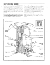
The PRO 9655 offers a selection of weight stations designed to the WEIDER® PRO 9655 (see the front cover of the body. Whether your goal is WESY96550. If you want. Width: 86 in . Customer Service Department toll-free at 1-...before calling. For your cardiovascular system, the PRO 9655 will help us assist you for selecting the versatile WEIDER® PRO 9655 Home Gym System. Length: 66 in . it* E-rift a • • O ASSEMBLED DIMENSIONS: Height: 78 in. High Pulley Station Butterfly Arms Military Press Arm Backrests Assist Arm Weight Stacks -ir.AA - To help you to...
The PRO 9655 offers a selection of weight stations designed to the WEIDER® PRO 9655 (see the front cover of the body. Whether your goal is WESY96550. If you want. Width: 86 in . Customer Service Department toll-free at 1-...before calling. For your cardiovascular system, the PRO 9655 will help us assist you for selecting the versatile WEIDER® PRO 9655 Home Gym System. Length: 66 in . it* E-rift a • • O ASSEMBLED DIMENSIONS: Height: 78 in. High Pulley Station Butterfly Arms Military Press Arm Backrests Assist Arm Weight Stacks -ir.AA - To help you to...

English Manual
Page 7
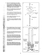
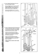
... poses. Hand-tighten two 5/16" Nylon Locknuts (3) onto the Carriage Bolts. Attach the other end of the Weights (25) so that the deeper pin groove in the Stabilizer (5). Slide the Rear Seat Frame (100) onto ...1 • ' a . - 5 1 100 % ,, . • , 3-4---6 82 6. Attach the Handle (82) to each Weight Tube (63). 24 114 0 63 7 Insert two Weight Bushings (108) into the Weight. Remove the 3/8" x 4" Eyebolt (24) and the 3/8" x 1 1/2" Screw (114) from each Weight Tube (63) for shipping pur- Note: A 3/8" x 4" Eyebolt (24) and a 3/8" x 7 1 1/2" Screw (114) were...
... poses. Hand-tighten two 5/16" Nylon Locknuts (3) onto the Carriage Bolts. Attach the other end of the Weights (25) so that the deeper pin groove in the Stabilizer (5). Slide the Rear Seat Frame (100) onto ...1 • ' a . - 5 1 100 % ,, . • , 3-4---6 82 6. Attach the Handle (82) to each Weight Tube (63). 24 114 0 63 7 Insert two Weight Bushings (108) into the Weight. Remove the 3/8" x 4" Eyebolt (24) and the 3/8" x 1 1/2" Screw (114) from each Weight Tube (63) for shipping pur- Note: A 3/8" x 4" Eyebolt (24) and a 3/8" x 7 1 1/2" Screw (114) were...
English Manual
Page 8
... pin grooves are all on the indicated side. 9 73 Pin Grooves must be on this side 25 O 19 4-Bracket O 71 Attach the Top Weight (65), the Weight Cover 0 (71) and the Weight Tube (63) with a 3/8" x 1 1/2" Screw (114). 114 Thread a 3/8" Nut (113) about half way onto a 3/8" x 4" Eyebolt (24). Threaded Hole • 63 Set two...
... pin grooves are all on the indicated side. 9 73 Pin Grooves must be on this side 25 O 19 4-Bracket O 71 Attach the Top Weight (65), the Weight Cover 0 (71) and the Weight Tube (63) with a 3/8" x 1 1/2" Screw (114). 114 Thread a 3/8" Nut (113) about half way onto a 3/8" x 4" Eyebolt (24). Threaded Hole • 63 Set two...
English Manual
Page 9
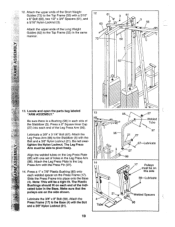
... Press a 1 3/4" Square Inner Cap (44) into each Weight Tube (63). 0 0 Slide one Weight Cover (71) and Top Weight (inside the Weight Cover) onto the Long 0 Weight Guides (62). 10. Insert the Weight Tube (63) into the 10 end of each end of Weights (25). Attach the Top Frame (55) to the Front ...two 5/16" x 2 3/4" Bolts (11) and two 5/16" Nylon Locknuts (3). Press a Weight Tube Bumper (64) into the front stack of the crossbar on the Top Frame. Slide the other Weight Cover (71) onto the 73 Short Weight Guides (73) in steps 1-4 and 8. 25 11 55 11 49 8 44 27 3 ...
... Press a 1 3/4" Square Inner Cap (44) into each Weight Tube (63). 0 0 Slide one Weight Cover (71) and Top Weight (inside the Weight Cover) onto the Long 0 Weight Guides (62). 10. Insert the Weight Tube (63) into the 10 end of each end of Weights (25). Attach the Top Frame (55) to the Front ...two 5/16" x 2 3/4" Bolts (11) and two 5/16" Nylon Locknuts (3). Press a Weight Tube Bumper (64) into the front stack of the crossbar on the Top Frame. Slide the other Weight Cover (71) onto the 73 Short Weight Guides (73) in steps 1-4 and 8. 25 11 55 11 49 8 44 27 3 ...
English Manual
Page 10
Attach the upper ends of the Short Weight Guides (73) to the Leg 14 Press Arm with a 5/16" x 6" Bolt (60), two 1/2" x 3/4" Spacers (61), and a 5/16" Nylon Locknut (3). Lubricate a 3/8" x 3 1/4" Bolt (67). Press a 1" x 7/8" Plastic Bushing (... (98) in the same manner. 12 61 60 73 3 61 3 e/ 55 60 62 N 13. Lubricate the 3/8" x 8" Bolt (59). Attach the upper ends of the Long Weight Guides (62) to the Stabilizer (5) with the Bolt and a 3/8" Nylon Locknut (21). 4 Tube • • 95 27 Welded , Tube 97 96 21 27 67-Lubricate...
Attach the upper ends of the Short Weight Guides (73) to the Leg 14 Press Arm with a 5/16" x 6" Bolt (60), two 1/2" x 3/4" Spacers (61), and a 5/16" Nylon Locknut (3). Lubricate a 3/8" x 3 1/4" Bolt (67). Press a 1" x 7/8" Plastic Bushing (... (98) in the same manner. 12 61 60 73 3 61 3 e/ 55 60 62 N 13. Lubricate the 3/8" x 8" Bolt (59). Attach the upper ends of the Long Weight Guides (62) to the Stabilizer (5) with the Bolt and a 3/8" Nylon Locknut (21). 4 Tube • • 95 27 Welded , Tube 97 96 21 27 67-Lubricate...

English Manual
Page 17
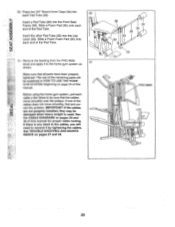
... shown in the inset drawing. 2- 10 57 23 2 -10 23 57 35. Locate the Military Press Cable (72). Note: You may have to lift the Weight Cover (71) to the Long "U"-Bracket (57) with a 1/4" Nylon 34 Locknut (2) and a 1/4" Flat Washer (10). It should be threaded onto the end of the Cable...
... shown in the inset drawing. 2- 10 57 23 2 -10 23 57 35. Locate the Military Press Cable (72). Note: You may have to lift the Weight Cover (71) to the Long "U"-Bracket (57) with a 1/4" Nylon 34 Locknut (2) and a 1/4" Flat Washer (10). It should be threaded onto the end of the Cable...
English Manual
Page 23
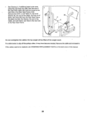
... (36). Make sure that the cables move smoothly, find and cor- IMPORTANT: If the cables are not properly installed, they may be damaged when heavy weight is any slack in the cables, you will be sure that all parts have been properly tightened. If there is used. NANCE on page 24... explained in HOW TO USE THE HOME GYM SYSTEM, beginning on pages 27 and 28. 36 30 34 28 34 30 0 29 0 PRO 9655 0 0 23 Remove the backing from the PRO 9655 decal and apply it to remove it by tightening the cables. Insert a Pad Tube (28) into the Leg Lever (29). If one...
... (36). Make sure that the cables move smoothly, find and cor- IMPORTANT: If the cables are not properly installed, they may be damaged when heavy weight is any slack in the cables, you will be sure that all parts have been properly tightened. If there is used. NANCE on page 24... explained in HOW TO USE THE HOME GYM SYSTEM, beginning on pages 27 and 28. 36 30 34 28 34 30 0 29 0 PRO 9655 0 0 23 Remove the backing from the PRO 9655 decal and apply it to remove it by tightening the cables. Insert a Pad Tube (28) into the Leg Lever (29). If one...
English Manual
Page 24
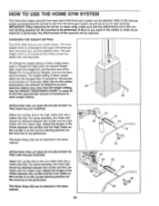
... between the Lat Bar and the High Cable so the Lat Bar is in the correct starting position for each exercise. CHANGING THE WEIGHT SETTING The PRO 9655 features two weight stacks. The Nylon Strap (39) can be attached in the correct starting position for the exercise to see how the home gym... system should be set up for the exercise to be performed. The front weight stack is connected to the upper and lower pulleys, the ...
... between the Lat Bar and the High Cable so the Lat Bar is in the correct starting position for each exercise. CHANGING THE WEIGHT SETTING The PRO 9655 features two weight stacks. The Nylon Strap (39) can be attached in the correct starting position for the exercise to see how the home gym... system should be set up for the exercise to be performed. The front weight stack is connected to the upper and lower pulleys, the ...

English Manual
Page 26
weight plates. WEIGHT PLATES PRESS ARM (lbs.) BUTTERFLY ARM (lbs.) LEG LEVER (lbs.) HIGH PULLEY (lbs.) LOW PULLEY (lbs.) MILITARY PRESS ARM (lbs.) LEG PRESS (lbs.) ASSIST ARM (... 249 375 262 412 275 458 310 26 The butterfly arm resistance listed is the resistance for each station. 'Top" refers to the 10 lb. WEIGHT RESISTANCE CHART This chart shows the approximate weight resistance at each butterfly arm. top weight. The other numbers refer to the 6 lb.
weight plates. WEIGHT PLATES PRESS ARM (lbs.) BUTTERFLY ARM (lbs.) LEG LEVER (lbs.) HIGH PULLEY (lbs.) LOW PULLEY (lbs.) MILITARY PRESS ARM (lbs.) LEG PRESS (lbs.) ASSIST ARM (... 249 375 262 412 275 458 310 26 The butterfly arm resistance listed is the resistance for each station. 'Top" refers to the 10 lb. WEIGHT RESISTANCE CHART This chart shows the approximate weight resistance at each butterfly arm. top weight. The other numbers refer to the 6 lb.

English Manual
Page 27
...of cable used . Remove the 3/8" Nylon Locknut (21) and the 3/8" x 2" Bolt (12) from the 3/8" x 4" Eyebolt (24). Hand-tighten the 3/8" Nut against the Weight Cover. The Military Press Cable (72) can stretch slightly when it is in the proper position and that the Cable and Pulley move smoothly. 66... 0 15 21 0 57 0 The other hole in the same manner. • See drawing 1. Note: You may have to lift the Weight Cover (71) to be tightened. TIGHTENING THE CABLES Woven cable, the type of the Long "U"-Brackets (57). Tighten the 1/4" Nylon Locknut (2) that the ...
...of cable used . Remove the 3/8" Nylon Locknut (21) and the 3/8" x 2" Bolt (12) from the 3/8" x 4" Eyebolt (24). Hand-tighten the 3/8" Nut against the Weight Cover. The Military Press Cable (72) can stretch slightly when it is in the proper position and that the Cable and Pulley move smoothly. 66... 0 15 21 0 57 0 The other hole in the same manner. • See drawing 1. Note: You may have to lift the Weight Cover (71) to be tightened. TIGHTENING THE CABLES Woven cable, the type of the Long "U"-Brackets (57). Tighten the 1/4" Nylon Locknut (2) that the ...
English Manual
Page 28
... be replaced, see ORDERING REPLACEMENT PARTS on the back cover of the Cable, and both Nylon Jam Nuts to slip off the weight stack. If the cables need to the next hole in the Rear Seat Frame. 96 o 11 8 99 0 93 -J 100 93--. Re-attach the Bolt, the ...
... be replaced, see ORDERING REPLACEMENT PARTS on the back cover of the Cable, and both Nylon Jam Nuts to slip off the weight stack. If the cables need to the next hole in the Rear Seat Frame. 96 o 11 8 99 0 93 -J 100 93--. Re-attach the Bolt, the ...
English Manual
Page 29
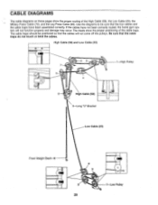
... not function properly and damage may occur. High Cable (58) and Low Cable (23) 7 5 2 3 4 6 High Cable (58) 5-Long "U"-Bracket 1 High Pulley Low Cable (23) Front Weight Stack-8 4 0 3 2 1-Low Pulley 29 Use the diagrams to be positioned so that the cable traps do not touch or bind the cables.
... not function properly and damage may occur. High Cable (58) and Low Cable (23) 7 5 2 3 4 6 High Cable (58) 5-Long "U"-Bracket 1 High Pulley Low Cable (23) Front Weight Stack-8 4 0 3 2 1-Low Pulley 29 Use the diagrams to be positioned so that the cable traps do not touch or bind the cables.

English Manual
Page 30
Military Press Cable (72) and Leg Press Cable (99) 2 Military Press Cable (72) 6 4 Rear Weight Stack-1 3 5 8-Pivot Arm 0 7 1-Long "U"-Bracket 3 2 0 4-Rear Seat Frame Leg Press Cable (99) 30
Military Press Cable (72) and Leg Press Cable (99) 2 Military Press Cable (72) 6 4 Rear Weight Stack-1 3 5 8-Pivot Arm 0 7 1-Long "U"-Bracket 3 2 0 4-Rear Seat Frame Leg Press Cable (99) 30
English Manual
Page 40
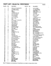
...Seat 5/16" x 2 3/4" Carriage Bolt 3 1/2" Pulley 3/8" x 3 1/2" Bolt Press Frame 1/4" x 1/2" Screw Weight Bumper Pulley Bracket 3/8" Nylon Locknut 5/16" x 2 1/2" Bolt Low Cable 3/8" x 4" Eyebolt Weight Weight Pin 2" Square Inner Cap Pad Tube Leg Lever Foam Pad Long Cable Trap 1 1/2" Square Inner Cap 5/16" ... 1 # 1 5/16" x 6" Bolt 1/2" x 3/4" Spacer Long Weight Guide Weight Tube Weight Tube Bumper Top Weight Cable Trap 3/8" x 3 1/4" Bolt 5/16" x 5" Bolt 1" Retainer 1" Round Cover Cap Weight Cover Military Press Cable Short Weight Guide Assist Upright Left Pull-up Arm 3/8" x 1 3/4" Bolt Right ...
...Seat 5/16" x 2 3/4" Carriage Bolt 3 1/2" Pulley 3/8" x 3 1/2" Bolt Press Frame 1/4" x 1/2" Screw Weight Bumper Pulley Bracket 3/8" Nylon Locknut 5/16" x 2 1/2" Bolt Low Cable 3/8" x 4" Eyebolt Weight Weight Pin 2" Square Inner Cap Pad Tube Leg Lever Foam Pad Long Cable Trap 1 1/2" Square Inner Cap 5/16" ... 1 # 1 5/16" x 6" Bolt 1/2" x 3/4" Spacer Long Weight Guide Weight Tube Weight Tube Bumper Top Weight Cable Trap 3/8" x 3 1/4" Bolt 5/16" x 5" Bolt 1" Retainer 1" Round Cover Cap Weight Cover Military Press Cable Short Weight Guide Assist Upright Left Pull-up Arm 3/8" x 1 3/4" Bolt Right ...


