
English Manual
Page 2
Remove the PART IDENTIFICATION CHART and the PART LIST/EXPLODED DRAWING before beginning assembly. TABLE OF CONTENTS IMPORTANT PRECAUTIONS 3 BEFORE YOU BEGIN 4 ASSEMBLY 5 HOW TO USE THE HOME GYM SYSTEM 22 WEIGHT RESISTANCE CHART 24 TROUBLESHOOTING AND MAINTENANCE 25 CABLE DIAGRAMS 26 ORDERING REPLACEMENT PARTS Back Cover LIMITED WARRANTY Back Cover Note: A PART IDENTIFICATION CHART and a PART LIST/EXPLODED DRAWING are attached to the center of ICON Health & Fitness, Inc. 2 WEIDER is a registered trademark of this manual.
Remove the PART IDENTIFICATION CHART and the PART LIST/EXPLODED DRAWING before beginning assembly. TABLE OF CONTENTS IMPORTANT PRECAUTIONS 3 BEFORE YOU BEGIN 4 ASSEMBLY 5 HOW TO USE THE HOME GYM SYSTEM 22 WEIGHT RESISTANCE CHART 24 TROUBLESHOOTING AND MAINTENANCE 25 CABLE DIAGRAMS 26 ORDERING REPLACEMENT PARTS Back Cover LIMITED WARRANTY Back Cover Note: A PART IDENTIFICATION CHART and a PART LIST/EXPLODED DRAWING are attached to the center of ICON Health & Fitness, Inc. 2 WEIDER is a registered trademark of this manual.
English Manual
Page 3
... lever, leg press plate, lat bar or nylon strap while weights are on a foot plate when performing an exercise that the cables are raised. If the cables bind while you are exercising, stop immediately and begin cooling down. Do not use the VKR station when either weight stack is .... 3. Always disconnect the lat bar from moving parts. 9. Keep hands and feet away from the home gym system when performing an exercise that the cables remain on a level surface. Make sure that does not use the lat bar. 15. WARNING: Before beginning this or any worn parts immediately. 6....
... lever, leg press plate, lat bar or nylon strap while weights are on a foot plate when performing an exercise that the cables are raised. If the cables bind while you are exercising, stop immediately and begin cooling down. Do not use the VKR station when either weight stack is .... 3. Always disconnect the lat bar from moving parts. 9. Keep hands and feet away from the home gym system when performing an exercise that the cables remain on a level surface. Make sure that does not use the lat bar. 15. WARNING: Before beginning this or any worn parts immediately. 6....
English Manual
Page 5
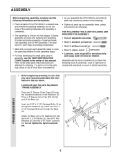
...see if it has been pre-attached. • As you have the following information and instructions: • Place all parts of the PRO 9635 in the drawings. • Tighten all parts are oriented as shown in a cleared area and remove the packing materials; The hardware for ...open the parts bag labeled "FRAME ASSEMBLY." Press a 2" Square Inner Cap (27) into five stages: 1) frame assembly, 2) press and butterfly arm assembly, 3) cable and pulley assembly, 4) seat and backrest assembly, and 5) VKR assembly. Insert two 5/16" x 2 1/2" Carriage Bolts up through the Base (4). Note: Some small...
...see if it has been pre-attached. • As you have the following information and instructions: • Place all parts of the PRO 9635 in the drawings. • Tighten all parts are oriented as shown in a cleared area and remove the packing materials; The hardware for ...open the parts bag labeled "FRAME ASSEMBLY." Press a 2" Square Inner Cap (27) into five stages: 1) frame assembly, 2) press and butterfly arm assembly, 3) cable and pulley assembly, 4) seat and backrest assembly, and 5) VKR assembly. Insert two 5/16" x 2 1/2" Carriage Bolts up through the Base (4). Note: Some small...
English Manual
Page 10
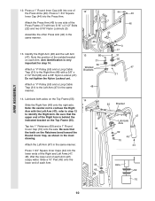
... one side of each Arm. 44 45 55 Bracket 47 Lubricate Axle 69 45 70 44 Axle 69 70 10 Attach a "V"-Pulley (50) and a Long Cable Trap (31) to one of each Arm with the Left Arm (47); Do not tighten the Nylon Locknut yet. 13 86 31 50 Welded Brackets...
... one side of each Arm. 44 45 55 Bracket 47 Lubricate Axle 69 45 70 44 Axle 69 70 10 Attach a "V"-Pulley (50) and a Long Cable Trap (31) to one of each Arm with the Left Arm (47); Do not tighten the Nylon Locknut yet. 13 86 31 50 Welded Brackets...
English Manual
Page 11
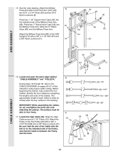
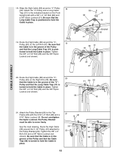
... Frame (55) with two 5/16" x 2 1/4" Bolts (33) and two 5/16" Nylon Locknuts (3). Attach the Military Press Arm (84) to verify proper cable routing. Wrap the High 21 Cable around a 3 1/2" Pulley (15). Slide two 5" Plastic Grips (83) onto the Military Press Arm. See the inset drawing. Press two 1 1/2" Square Inner... Caps (32) into 21 the Military Press Arm. Be sure that the Cable is listed (in inches) after the key number in the drawing. Press two 1" Round Inner Caps (49) into the indicated end of the...
... Frame (55) with two 5/16" x 2 1/4" Bolts (33) and two 5/16" Nylon Locknuts (3). Attach the Military Press Arm (84) to verify proper cable routing. Wrap the High 21 Cable around a 3 1/2" Pulley (15). Slide two 5" Plastic Grips (83) onto the Military Press Arm. See the inset drawing. Press two 1 1/2" Square Inner... Caps (32) into 21 the Military Press Arm. Be sure that the Cable is listed (in inches) after the key number in the drawing. Press two 1" Round Inner Caps (49) into the indicated end of the...
English Manual
Page 12
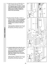
... is turned to the indicated bracket on the Right Arm (48). Attach the Pulley Bracket (20) to the Pulley Bracket (20). Route the High Cable (58) around the "V"- 20 Pulley (50) on the Front Upright (42) with the 5/16" x 5" Bolt (68) and a 68 5/16" Nylon Locknut (3). tioned to move freely. ... (86) and the 3/8" Nylon Locknut (not shown). 86 31 58 50 Bracket 42 21 86 31 50 58 47 20. Be sure that the Long Cable Trap (31) is in place. 12 Tighten the 3/8" x 2" 20 12 Bolt (12) and a 3/8" Nylon Locknut (not shown). Be sure that 19 the...
... is turned to the indicated bracket on the Right Arm (48). Attach the Pulley Bracket (20) to the Pulley Bracket (20). Route the High Cable (58) around the "V"- 20 Pulley (50) on the Front Upright (42) with the 5/16" x 5" Bolt (68) and a 68 5/16" Nylon Locknut (3). tioned to move freely. ... (86) and the 3/8" Nylon Locknut (not shown). 86 31 58 50 Bracket 42 21 86 31 50 58 47 20. Be sure that the Long Cable Trap (31) is in place. 12 Tighten the 3/8" x 2" 20 12 Bolt (12) and a 3/8" Nylon Locknut (not shown). Be sure that 19 the...
English Manual
Page 13
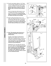
... Washer (9), the 5/8" x 9/16" Spacer (7), the 3 1/2" Low Pulley (76), and the 3/8" Nylon Locknut (21) are oriented as shown. 13 9 88 7 17 76 21 Wrap the High Cable (58) around a 3 1/2" Pulley (15). The Bolt has been shown removed for shipping purposes. See the inset drawing. Note: This may come pre-assembled. Remove the...) and the 3 1/2" Pulley (15) shown in a Long "U"-Bracket (57) with the 5/8" x 9/16" Spacer (7) between the Pulley and the Press Frame (17). Be sure that the Cable and Pulley move smoothly. 22 66 21 57 23 55 58 15 12 57 Bracket 58 15 58 12 15...
... Washer (9), the 5/8" x 9/16" Spacer (7), the 3 1/2" Low Pulley (76), and the 3/8" Nylon Locknut (21) are oriented as shown. 13 9 88 7 17 76 21 Wrap the High Cable (58) around a 3 1/2" Pulley (15). The Bolt has been shown removed for shipping purposes. See the inset drawing. Note: This may come pre-assembled. Remove the...) and the 3 1/2" Pulley (15) shown in a Long "U"-Bracket (57) with the 5/8" x 9/16" Spacer (7) between the Pulley and the Press Frame (17). Be sure that the Cable and Pulley move smoothly. 22 66 21 57 23 55 58 15 12 57 Bracket 58 15 58 12 15...
English Manual
Page 14
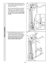
Crossbar 21 76 23 Ball 17 26. Tighten the 3/8" Nylon Locknut (21) and the 3/8" x 3 3/4" Bolt (not shown). Be sure that the Cable is on the Press Frame. Tighten the 3/8" Nylon Locknut (21) and the 3/8" x 3 1/2" Bolt (not shown). 23 15 21 66 17 28. Tighten the 3/8" Nylon Locknut (... the 3 1/2" Low Pulley (76) attached to the lower hole in the 27 Press Frame (17). Be sure that the 15 42 Cable is turned to the upper hole in the Front Upright (42). Tighten the 3/8" Nylon Locknut (21) and the 3/8" x 3 3/4" Bolt (88). 26 21 42 15 23 ...
Crossbar 21 76 23 Ball 17 26. Tighten the 3/8" Nylon Locknut (21) and the 3/8" x 3 3/4" Bolt (not shown). Be sure that the Cable is on the Press Frame. Tighten the 3/8" Nylon Locknut (21) and the 3/8" x 3 1/2" Bolt (not shown). 23 15 21 66 17 28. Tighten the 3/8" Nylon Locknut (... the 3 1/2" Low Pulley (76) attached to the lower hole in the 27 Press Frame (17). Be sure that the 15 42 Cable is turned to the upper hole in the Front Upright (42). Tighten the 3/8" Nylon Locknut (21) and the 3/8" x 3 3/4" Bolt (88). 26 21 42 15 23 ...
English Manual
Page 15
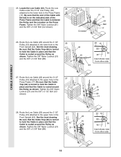
...a 5/16" x 1 3/4" Bolt (24) and a 5/16" Nylon Locknut (3). 2 2 10 10 57 58 3 71 63 58 71 10 2 31. Locate the Military Press Cable (72). pletely tighten the Nylon Locknut. Do not com- Attach the Small "U"-Bracket (71) to the indicated Weight Tube (63) with a 1/4" Nylon Locknut (2) 3 and a 1/4"... to the indi- 71 72 cated Weight Tube (63) with a 1/4" Nylon Locknut (2) and a 1/4" Flat Washer (10). CABLE ASSEMBLY 29. It should be threaded onto the end of the Cable only a couple of the Low Cable (23) to the 29 Long "U"-Bracket (57) with a 5/16" x 1 3/4" Bolt (24) and a 5/16" ...
...a 5/16" x 1 3/4" Bolt (24) and a 5/16" Nylon Locknut (3). 2 2 10 10 57 58 3 71 63 58 71 10 2 31. Locate the Military Press Cable (72). pletely tighten the Nylon Locknut. Do not com- Attach the Small "U"-Bracket (71) to the indicated Weight Tube (63) with a 1/4" Nylon Locknut (2) 3 and a 1/4"... to the indi- 71 72 cated Weight Tube (63) with a 1/4" Nylon Locknut (2) and a 1/4" Flat Washer (10). CABLE ASSEMBLY 29. It should be threaded onto the end of the Cable only a couple of the Low Cable (23) to the 29 Long "U"-Bracket (57) with a 5/16" x 1 3/4" Bolt (24) and a 5/16" ...
English Manual
Page 16
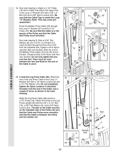
... (66) to the bracket on the side shown and that the Cable Trap is turned to hold the Cable in place. 33 15 88 66 9 101 72 21 CABLE ASSEMBLY 16 Be sure that the Nylon Locknut is positioned to hold the Cable in place. 32 55 15 21 12 72 72 12 66... 15 Bracket 21 5 33. 32. Be sure that the Cable Trap is on the Stabilizer (5) with a 3/8" x 2" Bolt (12) and a 3/8" Nylon Locknut (21). Wrap the Military Press Cable (72) around a 3 1/2" Pulley (15). Wrap the Military Press Cable (72) around a 3 1/2" Pulley (15). Attach the Pulley to the Pivot Arm (101) with...
... (66) to the bracket on the side shown and that the Cable Trap is turned to hold the Cable in place. 33 15 88 66 9 101 72 21 CABLE ASSEMBLY 16 Be sure that the Nylon Locknut is positioned to hold the Cable in place. 32 55 15 21 12 72 72 12 66... 15 Bracket 21 5 33. 32. Be sure that the Cable Trap is on the Stabilizer (5) with a 3/8" x 2" Bolt (12) and a 3/8" Nylon Locknut (21). Wrap the Military Press Cable (72) around a 3 1/2" Pulley (15). Wrap the Military Press Cable (72) around a 3 1/2" Pulley (15). Attach the Pulley to the Pivot Arm (101) with...
English Manual
Page 17
...with a 1/4" Nylon Locknut (2) and a 1/4" Flat Washer (10). It should be threaded onto the end of the Cable only a couple of the Bolt. The ball on the Cable must be on the indicated side of the Cable to the Long "U"- See inset drawing A. Thread another 5/16" Nylon Jam Nut onto the Bolt. Attach a 3... between the Pulley and the welded rod. 2 10 57 16 15 99 17 99 Welded 2 Rod 10 57 56 Ball 9 21 Wrap the Leg Press Cable (99) around a 3 1/2" Pulley (15). Insert the Bolt through the Long "U"-Bracket (57) and the 3 1/2" Pulley (15). Attach the Pulley to the upper ...
...with a 1/4" Nylon Locknut (2) and a 1/4" Flat Washer (10). It should be threaded onto the end of the Cable only a couple of the Bolt. The ball on the Cable must be on the indicated side of the Cable to the Long "U"- See inset drawing A. Thread another 5/16" Nylon Jam Nut onto the Bolt. Attach a 3... between the Pulley and the welded rod. 2 10 57 16 15 99 17 99 Welded 2 Rod 10 57 56 Ball 9 21 Wrap the Leg Press Cable (99) around a 3 1/2" Pulley (15). Insert the Bolt through the Long "U"-Bracket (57) and the 3 1/2" Pulley (15). Attach the Pulley to the upper ...
English Manual
Page 18
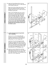
... Backrest (85) with a 5/16" x 3" Bolt (75) and a 5/16" Nylon Locknut (3). Attach the other end of the Bolt. Slide the end of the Leg Press Cable (99) onto the end of the Seat to the Leg 36 Press Arm (96) with two 1/4" x 3/4" Screws (18). Insert the 1/4" x 2 1/2" Carriage Bolt (92).... 96 12 11 3 8 99 94 75 15 21 100 93 SEAT ASSEMBLY 37. Wrap the Leg Press Cable (99) around a 3 1/2" Pulley (15). Locate and open the parts bag labeled "SEAT ASSEMBLY." CABLE ASSEMBLY 36. Insert the Bolt through the lowest hole in the Leg Press Upright (56). Tighten a 1/4" Nylon...
... Backrest (85) with a 5/16" x 3" Bolt (75) and a 5/16" Nylon Locknut (3). Attach the other end of the Bolt. Slide the end of the Leg Press Cable (99) onto the end of the Seat to the Leg 36 Press Arm (96) with two 1/4" x 3/4" Screws (18). Insert the 1/4" x 2 1/2" Carriage Bolt (92).... 96 12 11 3 8 99 94 75 15 21 100 93 SEAT ASSEMBLY 37. Wrap the Leg Press Cable (99) around a 3 1/2" Pulley (15). Locate and open the parts bag labeled "SEAT ASSEMBLY." CABLE ASSEMBLY 36. Insert the Bolt through the lowest hole in the Leg Press Upright (56). Tighten a 1/4" Nylon...
English Manual
Page 21
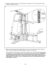
... and 27 of the remaining parts will be explained in the cables, you will need to the Front Upright (42) under the "WEIDER" nameplate as shown. 46 WEIDER Nameplate 42 PRO 9635 Decal 47. If one of this manual for proper cable routing. IMPORTANT: If the cables are not properly installed, they may be sure that all...
... and 27 of the remaining parts will be explained in the cables, you will need to the Front Upright (42) under the "WEIDER" nameplate as shown. 46 WEIDER Nameplate 42 PRO 9635 Decal 47. If one of this manual for proper cable routing. IMPORTANT: If the cables are not properly installed, they may be sure that all...
English Manual
Page 22
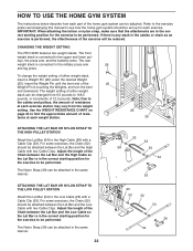
Adjust the length of the Chain between the Lat Bar and the High Cable with two Cable Clips. The Nylon Strap (39) can be changed from the weight setting. CHANGING THE WEIGHT SETTING The PRO 9635 features two weight stacks. Insert the Weight Pin until the bent end of the 25 Weight Pin is ...the attachments are in the correct starting position for each exercise. Adjust the length of the Chain between the Lat Bar and the Low Cable with two Cable Clips. HOW TO USE THE HOME GYM SYSTEM The instructions below describe how each part of the home gym system can be attached in...
Adjust the length of the Chain between the Lat Bar and the High Cable with two Cable Clips. The Nylon Strap (39) can be changed from the weight setting. CHANGING THE WEIGHT SETTING The PRO 9635 features two weight stacks. Insert the Weight Pin until the bent end of the 25 Weight Pin is ...the attachments are in the correct starting position for each exercise. Adjust the length of the Chain between the Lat Bar and the Low Cable with two Cable Clips. HOW TO USE THE HOME GYM SYSTEM The instructions below describe how each part of the home gym system can be attached in...
English Manual
Page 23
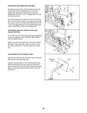
... on Leg Press Plate and the holes in the Leg Press Arm (96). Attach one end of the Chain (52) to the Front Upright with a Cable Clip (53). ADJUSTING THE LEG PRESS PLATE Remove the Press Pin (97) from the Seat Frame (36). ATTACHING AND REMOVING THE SEAT To attach the... Arm. 40 36 13 42 14 53 52 29 35 53 23 Welded Tube 96 95 97 23 Attach the Seat Frame to the Short Cable (23) with the 5/16" x 2 3/4" Carriage Bolt (14) and the Seat Knob (40). Re-insert the Press Pin (97) through the welded tubes on the Leg...
... on Leg Press Plate and the holes in the Leg Press Arm (96). Attach one end of the Chain (52) to the Front Upright with a Cable Clip (53). ADJUSTING THE LEG PRESS PLATE Remove the Press Pin (97) from the Seat Frame (36). ATTACHING AND REMOVING THE SEAT To attach the... Arm. 40 36 13 42 14 53 52 29 35 53 23 Welded Tube 96 95 97 23 Attach the Seat Frame to the Short Cable (23) with the 5/16" x 2 3/4" Carriage Bolt (14) and the Seat Knob (40). Re-insert the Press Pin (97) through the welded tubes on the Leg...
English Manual
Page 24
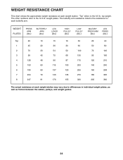
... chart shows the approximate weight resistance at each weight station may vary due to differences in individual weight plates, as well as friction between the cables, pulleys, and weight guides. 24
... chart shows the approximate weight resistance at each weight station may vary due to differences in individual weight plates, as well as friction between the cables, pulleys, and weight guides. 24
English Manual
Page 25
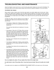
... stack, both 5/16" Nylon Jam Nuts (93) from the Rear Seat Frame. If any worn parts immediately. Reattach the Pulley and Cable Trap. If additional slack is felt, the cables should be tightened. The top weight will be moved to be tightened. Replace any slack is felt when using the Leg Press... Arm (96), then the end of the Leg Press Cable (99) must be lifted off the pulleys often, it may have become twisted. If any slack is felt when using a damp cloth and mild non...
... stack, both 5/16" Nylon Jam Nuts (93) from the Rear Seat Frame. If any worn parts immediately. Reattach the Pulley and Cable Trap. If additional slack is felt, the cables should be tightened. The top weight will be moved to be tightened. Replace any slack is felt when using the Leg Press... Arm (96), then the end of the Leg Press Cable (99) must be lifted off the pulleys often, it may have become twisted. If any slack is felt when using a damp cloth and mild non...
English Manual
Page 26
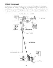
...) 7 5 23 4 1-High Pulley TOP VIEW 6 High Cable (58) 5-Long "U"-Bracket Low Cable (23) Front Weight Stack-8 4 3 2 1-Low Pulley 26 CABLE DIAGRAMS The cable diagrams on these pages show the proper positioning of the High Cable (58), the Low Cable (23), the Military Press Cable (72), and the Leg Press Cable (99). The cable traps should be sure that the...
...) 7 5 23 4 1-High Pulley TOP VIEW 6 High Cable (58) 5-Long "U"-Bracket Low Cable (23) Front Weight Stack-8 4 3 2 1-Low Pulley 26 CABLE DIAGRAMS The cable diagrams on these pages show the proper positioning of the High Cable (58), the Low Cable (23), the Military Press Cable (72), and the Leg Press Cable (99). The cable traps should be sure that the...
English Manual
Page 27
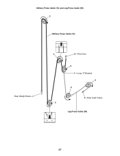
Military Press Cable (72) and Leg Press Cable (99) 2 Military Press Cable (72) Rear Weight Stack-1 4 6-Pivot Arm 5 1-Long "U"-Bracket 3 2 4-Rear Seat Frame 3 Leg Press Cable (99) 27
Military Press Cable (72) and Leg Press Cable (99) 2 Military Press Cable (72) Rear Weight Stack-1 4 6-Pivot Arm 5 1-Long "U"-Bracket 3 2 4-Rear Seat Frame 3 Leg Press Cable (99) 27
English Manual
Page 29
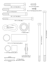
3/8" x 3 1/4" Bolt (67)-2 3/8" x 3 1/2" Bolt (16)-2 1/4" x 3/4" Screw (18)-6 #8 x 1/2" Self-tapping Screw (87)-2 3/8" x 3 3/4" Bolt (88)-5 5/16" x 5" Bolt (68)-1 Cable Clip (53)-3 1" Retainer (69)-4 5/16" x 6" Bolt (60)-2 3/8" x 8" Bolt (59)-1 1 1/8" x 2 1/2" Plastic Bushing (89)-2 1" x 7/8" Plastic Bushing (90)-2 3 1/2" Pulley (15)-13 (Not shown to scale) "V"-Pulley (50)-3 (Not shown to scale)
3/8" x 3 1/4" Bolt (67)-2 3/8" x 3 1/2" Bolt (16)-2 1/4" x 3/4" Screw (18)-6 #8 x 1/2" Self-tapping Screw (87)-2 3/8" x 3 3/4" Bolt (88)-5 5/16" x 5" Bolt (68)-1 Cable Clip (53)-3 1" Retainer (69)-4 5/16" x 6" Bolt (60)-2 3/8" x 8" Bolt (59)-1 1 1/8" x 2 1/2" Plastic Bushing (89)-2 1" x 7/8" Plastic Bushing (90)-2 3 1/2" Pulley (15)-13 (Not shown to scale) "V"-Pulley (50)-3 (Not shown to scale)


