
English Manual
Page 2
WEIDER is a registered trademark of this manual. TABLE OF CONTENTS IMPORTANT PRECAUTIONS 3 BEFORE YOU BEGIN 4 ASSEMBLY 5 HOW TO USE THE HOME GYM SYSTEM 22 WEIGHT RESISTANCE CHART 24 TROUBLESHOOTING AND MAINTENANCE 25 CABLE DIAGRAMS 26 ORDERING REPLACEMENT PARTS Back Cover LIMITED WARRANTY Back Cover Note: A PART IDENTIFICATION CHART and a PART LIST/EXPLODED DRAWING are attached to the center of ICON Health & Fitness, Inc. 2 Remove the PART IDENTIFICATION CHART and the PART LIST/EXPLODED DRAWING before beginning assembly.
WEIDER is a registered trademark of this manual. TABLE OF CONTENTS IMPORTANT PRECAUTIONS 3 BEFORE YOU BEGIN 4 ASSEMBLY 5 HOW TO USE THE HOME GYM SYSTEM 22 WEIGHT RESISTANCE CHART 24 TROUBLESHOOTING AND MAINTENANCE 25 CABLE DIAGRAMS 26 ORDERING REPLACEMENT PARTS Back Cover LIMITED WARRANTY Back Cover Note: A PART IDENTIFICATION CHART and a PART LIST/EXPLODED DRAWING are attached to the center of ICON Health & Fitness, Inc. 2 Remove the PART IDENTIFICATION CHART and the PART LIST/EXPLODED DRAWING before beginning assembly.
English Manual
Page 5
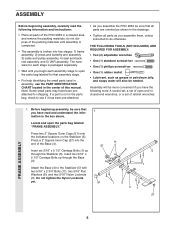
... screwdriver • One (1) rubber mallet • Lubricant, such as you assemble the PRO 9635 be needed. Assembly will also be sure that all parts are oriented as shown in a cleared... area and remove the packing materials; Insert six 5/16" x 2 1/2" Carriage Bolts (1) up through the Stabilizer (5). do otherwise. Press a 2" Square Inner Cap (27) into five stages: 1) frame assembly, 2) press and butterfly arm assembly, 3) cable and pulley assembly, 4) seat and backrest assembly...
... screwdriver • One (1) rubber mallet • Lubricant, such as you assemble the PRO 9635 be needed. Assembly will also be sure that all parts are oriented as shown in a cleared... area and remove the packing materials; Insert six 5/16" x 2 1/2" Carriage Bolts (1) up through the Stabilizer (5). do otherwise. Press a 2" Square Inner Cap (27) into five stages: 1) frame assembly, 2) press and butterfly arm assembly, 3) cable and pulley assembly, 4) seat and backrest assembly...
English Manual
Page 10
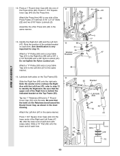
...Locknut yet. 13 86 31 50 Welded Brackets 31 50 47 21 Attach a "V"-Pulley (50) and a Long Cable Trap (31) to the Left Arm (47) in the same manner. Be sure that the upper end of... Identify the Right Arm (48) and the Left Arm (47). Attach a "V"-Pulley (50) and a Long Cable Trap (31) to one of each Arm. 44 45 55 Bracket 47 Lubricate Axle 69 45 70 44 Axle 69... to step 13 to confuse the Right Arm with a 3/8" x 2 1/2" Bolt (86) and a 3/8" Nylon Locknut (21). ARM ASSEMBLY 12. Press a 1" Round Inner Cap (49) into the lower ends of the 46 Press Frame (17) with soapy water. Press ...
...Locknut yet. 13 86 31 50 Welded Brackets 31 50 47 21 Attach a "V"-Pulley (50) and a Long Cable Trap (31) to the Left Arm (47) in the same manner. Be sure that the upper end of... Identify the Right Arm (48) and the Left Arm (47). Attach a "V"-Pulley (50) and a Long Cable Trap (31) to one of each Arm. 44 45 55 Bracket 47 Lubricate Axle 69 45 70 44 Axle 69... to step 13 to confuse the Right Arm with a 3/8" x 2 1/2" Bolt (86) and a 3/8" Nylon Locknut (21). ARM ASSEMBLY 12. Press a 1" Round Inner Cap (49) into the lower ends of the 46 Press Frame (17) with soapy water. Press ...
English Manual
Page 11
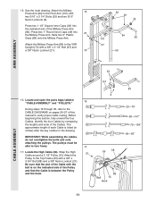
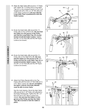
... (101) with a 3/8" x 3 3/4" Bolt (88) and a 3/8" Nylon Locknut (21). The approximate length of the Cable with a 3/8" x 3 1/4" Bolt (67) and a 3/8" Nylon Locknut (21). 74 32 49 32 84 101 83 67 56 ARM ASSEMBLY CABLE ASSEMBLY 33 101 16. Locate the High Cable (58). 15. See the inset drawing. Slide two 5" Plastic Grips (83) onto the Military...
... (101) with a 3/8" x 3 3/4" Bolt (88) and a 3/8" Nylon Locknut (21). The approximate length of the Cable with a 3/8" x 3 1/4" Bolt (67) and a 3/8" Nylon Locknut (21). 74 32 49 32 84 101 83 67 56 ARM ASSEMBLY CABLE ASSEMBLY 33 101 16. Locate the High Cable (58). 15. See the inset drawing. Slide two 5" Plastic Grips (83) onto the Military...
English Manual
Page 12
... of the "V"- Be sure that the Cable is in the groove of the Pulley and that the Long Cable Trap (31) is turned to the Pulley Bracket (20). Tighten the 3/8" x 2 1/2" Bolt (86) and the 3/8" Nylon Locknut (not shown). 58 31 86 50 48 CABLE ASSEMBLY 21. See the inset drawing. 18.... Be sure that the Long Cable Trap (31) is positioned to the indicated bracket on the Front Upright (42) with the 5/16" x 5" Bolt (68) and a...
... of the "V"- Be sure that the Cable is in the groove of the Pulley and that the Long Cable Trap (31) is turned to the Pulley Bracket (20). Tighten the 3/8" x 2 1/2" Bolt (86) and the 3/8" Nylon Locknut (not shown). 58 31 86 50 48 CABLE ASSEMBLY 21. See the inset drawing. 18.... Be sure that the Long Cable Trap (31) is positioned to the indicated bracket on the Front Upright (42) with the 5/16" x 5" Bolt (68) and a...
English Manual
Page 13
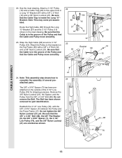
... 7 17 76 21 Do not remove the Bolt. Be sure that the Cable and Pulley move smoothly. 22 66 21 57 23 55 58 15 12 57 Bracket 58 15 58 12 15 CABLE ASSEMBLY 21 24. Attach a 3 1/2" Pulley (15) and a Cable Trap (66) to the upper hole in the inset drawing. Note: This... may come pre-assembled. Wrap the High Cable (58) around a 3 1/2" Pulley (15). The Bolt has been shown removed for shipping purposes...
... 7 17 76 21 Do not remove the Bolt. Be sure that the Cable and Pulley move smoothly. 22 66 21 57 23 55 58 15 12 57 Bracket 58 15 58 12 15 CABLE ASSEMBLY 21 24. Attach a 3 1/2" Pulley (15) and a Cable Trap (66) to the upper hole in the inset drawing. Note: This... may come pre-assembled. Wrap the High Cable (58) around a 3 1/2" Pulley (15). The Bolt has been shown removed for shipping purposes...
English Manual
Page 14
... Frame (17). Route the Low Cable (23) around the 3 1/2" 28 Pulley (15) attached to the upper hole in place and that the Cable Trap (66) is between the Pulley and the crossbar on the indicated side of the Cable with the ball is on the Press Frame. CABLE ASSEMBLY 25. See the inset drawing.... Be sure that the Cable is routed around the Pulley as shown. Route the...
... Frame (17). Route the Low Cable (23) around the 3 1/2" 28 Pulley (15) attached to the upper hole in place and that the Cable Trap (66) is between the Pulley and the crossbar on the indicated side of the Cable with the ball is on the Press Frame. CABLE ASSEMBLY 25. See the inset drawing.... Be sure that the Cable is routed around the Pulley as shown. Route the...
English Manual
Page 15
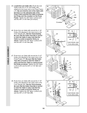
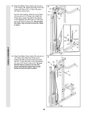
CABLE ASSEMBLY 29. Attach the High Cable (58) to the indicated Weight Tube (63) with a 5/16" x 1 3/4" Bolt (24) and a 5/16" Nylon Locknut (3). 2 2 10 10 57 58 3 71 63 58 71 10 2 31. Locate the Military Press Cable (72). Do not com- pletely tighten the Nylon Locknut. It ... Nylon Locknut (2) and a 1/4" Flat Washer (10). Do not completely tighten the Nylon Locknut. It should be threaded onto the end of the Cable only a couple of the Low Cable (23) to the 29 Long "U"-Bracket (57) with a 1/4" Nylon Locknut (2) 3 and a 1/4" Flat Washer (10). Do not completely tighten...
CABLE ASSEMBLY 29. Attach the High Cable (58) to the indicated Weight Tube (63) with a 5/16" x 1 3/4" Bolt (24) and a 5/16" Nylon Locknut (3). 2 2 10 10 57 58 3 71 63 58 71 10 2 31. Locate the Military Press Cable (72). Do not com- pletely tighten the Nylon Locknut. It ... Nylon Locknut (2) and a 1/4" Flat Washer (10). Do not completely tighten the Nylon Locknut. It should be threaded onto the end of the Cable only a couple of the Low Cable (23) to the 29 Long "U"-Bracket (57) with a 1/4" Nylon Locknut (2) 3 and a 1/4" Flat Washer (10). Do not completely tighten...
English Manual
Page 16
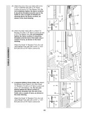
... (5) with a 3/8" x 2" Bolt (12) and a 3/8" Nylon Locknut (21). Wrap the Military Press Cable (72) around a 3 1/2" Pulley (15). Attach the Pulley and a Cable Trap (66) to hold the Cable in place. 33 15 88 66 9 101 72 21 CABLE ASSEMBLY 16 Attach the Pulley and a Cable Trap (66) to the Top Frame (55) with the 3/8" x 3 3/4" Bolt (88), a 3/8" Flat...
... (5) with a 3/8" x 2" Bolt (12) and a 3/8" Nylon Locknut (21). Wrap the Military Press Cable (72) around a 3 1/2" Pulley (15). Attach the Pulley and a Cable Trap (66) to hold the Cable in place. 33 15 88 66 9 101 72 21 CABLE ASSEMBLY 16 Attach the Pulley and a Cable Trap (66) to the Top Frame (55) with the 3/8" x 3 3/4" Bolt (88), a 3/8" Flat...
English Manual
Page 17
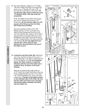
..." Nylon Jam Nut (93) onto the Bolt. Slide the end of the Military Press Cable (72) onto the end of the Leg Press Cable to pivot. 15 57 72 21 57 11 8 15 A 66 12 B 101 93 72 CABLE ASSEMBLY 35. Do not fully tighten the second Jam Nut. Attach the Pulley to the... upper hole in the Long "U"-Bracket (57) with a 3/8" x 2" Bolt (12) and a 3/8" Nylon Locknut (21). Be sure that the Cable is between the two Jam Nuts for the end...
..." Nylon Jam Nut (93) onto the Bolt. Slide the end of the Military Press Cable (72) onto the end of the Leg Press Cable to pivot. 15 57 72 21 57 11 8 15 A 66 12 B 101 93 72 CABLE ASSEMBLY 35. Do not fully tighten the second Jam Nut. Attach the Pulley to the... upper hole in the Long "U"-Bracket (57) with a 3/8" x 2" Bolt (12) and a 3/8" Nylon Locknut (21). Be sure that the Cable is between the two Jam Nuts for the end...
English Manual
Page 18
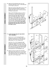
... the Seat Plate to the Leg 36 Press Arm (96) with a 1/4" x 2 1/2" Screw (43) and a 1/4" Flat Washer (10). 38. CABLE ASSEMBLY 36. There must be room between the two Jam Nuts for cable adjustment.) Tighten a 5/16" Nylon Jam Nut (93) onto the Bolt. Insert the 1/4" x 2 1/2" Carriage Bolt (92) through the center hole in...the end of the Seat to the Press Bracket (94) with a 1/4" Flat Washer (10) onto the Carriage Bolt. Attach the other end of the Cable to the Rear Seat Frame (100) with two 1/4" x 3/4" Screws (18). Do not fully tighten the second Jam Nut. Wrap the Leg Press...
... the Seat Plate to the Leg 36 Press Arm (96) with a 1/4" x 2 1/2" Screw (43) and a 1/4" Flat Washer (10). 38. CABLE ASSEMBLY 36. There must be room between the two Jam Nuts for cable adjustment.) Tighten a 5/16" Nylon Jam Nut (93) onto the Bolt. Insert the 1/4" x 2 1/2" Carriage Bolt (92) through the center hole in...the end of the Seat to the Press Bracket (94) with a 1/4" Flat Washer (10) onto the Carriage Bolt. Attach the other end of the Cable to the Rear Seat Frame (100) with two 1/4" x 3/4" Screws (18). Do not fully tighten the second Jam Nut. Wrap the Leg Press...
English Manual
Page 26
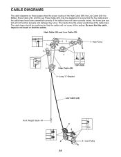
... on these pages show the proper positioning of the High Cable (58), the Low Cable (23), the Military Press Cable (72), and the Leg Press Cable (99). If the cables have been assembled correctly. Use the diagrams to be positioned so that the four cables and the cable traps have not been correctly routed, the home gym system...
... on these pages show the proper positioning of the High Cable (58), the Low Cable (23), the Military Press Cable (72), and the Leg Press Cable (99). If the cables have been assembled correctly. Use the diagrams to be positioned so that the four cables and the cable traps have not been correctly routed, the home gym system...


