
Weider Pro 4250 Support Question
Weider Pro 4250 Support Question
Find answers below for this question about Weider Pro 4250.Need a Weider Pro 4250 manual? We have 1 online manual for this item!
Question posted by jawsaw0328 on August 19th, 2015
Cable Assembly
how do I run the cable assembly on the weider pro 4250?the diagrams seem to stop mid air.
Current Answers
Answer #1: Posted by TommyKervz on August 29th, 2015 9:49 AM
TommyKervz

Member since:
January 10th, 2013 Points: 17,776,833

Member since:
January 10th, 2013 Points: 17,776,833
Refer to page 12 below
http://www.manualslib.com/manual/511399/Weider-Pro-4250.html?page=12#manual
Related Weider Pro 4250 Manual Pages
English Manual - Page 1
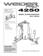
... in this manual before using this manual for reference. Patent Pending Sears, Roebuck and Co., Hoffman Estates, IL 60179 WEIGHT SYSTEM EXERCISER User's Manual
Serial Number Decal (under seat)
• Assembly • Adjustments • Troubleshooting • Part List and Drawing
CAUTION
Read all precautions and instructions in the space above for future...
English Manual - Page 2
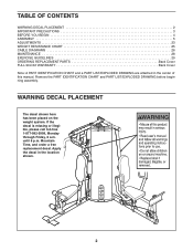
TABLE OF CONTENTS
WARNING DECAL PLACEMENT 2 IMPORTANT PRECAUTIONS 3 BEFORE YOU BEGIN 4 ASSEMBLY 5 ADJUSTMENTS 23 WEIGHT RESISTANCE CHART 25 CABLE DIAGRAMS 26 MAINTENANCE 28 EXERCISE GUIDELINES 29 ORDERING REPLACEMENT PARTS Back Cover FULL 90-DAY WARRANTY Back Cover Note: A PART IDENTIFICATION CHART and a PART LIST/EXPLODED DRAWING are attached in ...
English Manual - Page 3
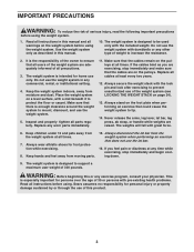
...system.
1. Make sure that the cables remain on the pulleys at any exercise program, consult your physician. Always stand on the foot plate when performing an exercise that does not use of the ...from the weight system when performing an exercise that could cause the weight system to mount, dismount, and use of this or any time while exercising, stop immediately and make sure that all ...
English Manual - Page 4
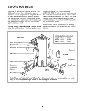
... build dramatic muscle size and strength, or improve your benefit, read this manual for selecting the versatile WEIDER® PRO 4250 weight system. The serial number can be found on a seat; For your cardiovascular system, the weight...Pulley Station
Backrest
Seat Leg Lever Low Pulley Station Foot Plate
ASSEMBLED DIMENSIONS: Height: 77 in. / 196 cm Width: 81 in. / 206 cm Depth: 59 in the ...
English Manual - Page 5
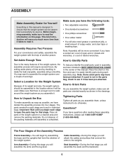
... -end or closed-end wrenches, or a set of the weight system. Important: Wait until assembly is enough room to do otherwise. Place all parts of the Assembly Process
Frame Assembly-You will require several hours.
Cable Assembly-During this stage you assemble the weight system, make sure all parts as shown in the drawings. You may...
English Manual - Page 6
...(1) with two M8 x 77mm Bolts (82), two M8 Washers
(98), and two M8 Nylon Locknuts (91).
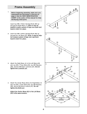
Frame Assembly
1
1. Note: It may be helpful to the Left Base (25)
3
with two M8 x 77mm Bolts (82... (91). Insert four M8 x 72mm Carriage Bolts (69) up through the Left Base (25). Before beginning assembly, make sure you understand the information in the same manner.
4
82 98 1 98
69
98 91
82
...
English Manual - Page 10
... the hole in steps 3-14.
14
82
98 98
5
91
91 98
85 98
91 2
14
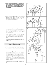
Arm Assembly
15. Slide a Large Foam Pad (15) onto the Left Butterfly Arm. Make sure the bolt head fits inside of the Left Butterfly Arm (6) with a grease packet.
Note: an entire grease packet should be used...
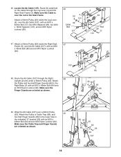
English Manual - Page 12
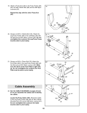
...). Do not overtighten the Locknut; See the CABLE DIAGRAMS on the Foot Plate is right side
up. the Cable must be able to identify the cables. Locate the Press Cable (109). the Foot
Plate must be able ...90). Attach the Cable to pivot easily.
90 25
72
90 Grease 76
38 28
Cable Assembly
22
22. 19. Make
sure the decal on pages 26 and 27 as you assemble the cables and to pivot ...
English Manual - Page 13
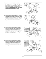
...Press Frame (29) with an M10 x 106mm Bolt (72) and an M10 Nylon Locknut (90). Wrap the Press Cable (109) around a 90mm Pulley (63). Make sure the Finger Guards are oriented as shown.
23
27
90
66 ...
29 109
66 70
66 99 63 68
13 Wrap the Press Cable (109) around a 90mm
26
Pulley (63). Attach the Pulley, two Half Finger Guards (66), a Cable Trap (68), and an M10 Washer (99) to the Leg ...
English Manual - Page 14
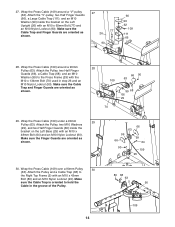
... (26) with an M10 x
48mm Bolt (64) and an M10 Nylon Locknut (90). Wrap the Press Cable (109) around a "V"-pulley (62). Attach the Pulley, two M10 Washers
(99), and two Half Finger Guards...(80) and an M10 Nylon Locknut (90). Wrap the Press Cable (109) under a 90mm
29
Pulley (63). Attach the Pulley, two Half Finger Guards (66), a Cable Trap (68), and an M10 Washer (99) to
the Right ...
English Manual - Page 15
...Upright (2) with
an M10 x 46mm Bolt (84) and an M10 Nylon
Locknut (90). Attach the "V"-pulley, a Large Cable Trap
(111), an M10 Washer (99), and two Full Finger
Guards (104) to the Double "U"-bracket (61) with an...Finger Guards are
oriented as shown in the inset drawing.
32. Attach the "V"-pulley, a Large Cable Trap
(111), an M10 Washer (99), and two Full Finger
Guards (104) to
the ...
English Manual - Page 16
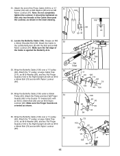
...
63
61 66
84
98 108 50
91
108 91
40. Note: Do not completely
tighten the Locknut; Attach the Cable
37
to the Double "U"-bracket (61) with an M10 x 80mm Bolt (75), two
M10 Washers (99), two...M10 Nylon Locknut (90).
16
99
75 102 5
110 63
99 102
90 Locate the Short Cable (108). Attach the end of the Short Cable (108) to the Right Butterfly
Arm (7) with an M8 Washer (98) and an M8
Nylon...
English Manual - Page 17

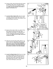
...102), and an
M10 Nylon Locknut (90).
75 99
102 99 90
63 110
5
42. Make sure the Cable Trap is oriented to the indicated bracket on top of turns.
80 63 110 Bracket
80 5 63
68 110 ...the Right Top Frame (5) with an M10 x 43mm
Bolt (80) and an M10 Nylon Locknut (90). Wrap the Weight Cable (110) under a 90mm
42
Pulley (63). Bracket 5
110 64
63
66
66
90
68
51
51
90
44.
...
English Manual - Page 18
...(80) and an M10 Nylon Locknut
(90). 90
63 3
107 80
48. Make sure the Cable is over the Ab Cable (107), with an M10 x
48mm Bolt (64) and an M10 Nylon Locknut (90). Route the small ...(3). Attach a 90mm Pulley (63) inside the Leg Lever (4), over a 90mm Pulley (63). Wrap the Ab Cable (107) over the Ab Cable (107), with an M10 x 48mm Bolt (64) and
an M10 Nylon Locknut (90). 46. Make sure the...
English Manual - Page 20
... (90). Tighten the M12 Nut (49) on the
Weight Cable against the M12 Washer (33).
90 99
107 2
Rod 105 63 105
72
110
33
49
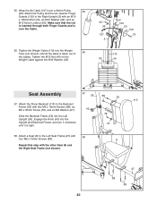
Seat Assembly
57
26
88
53
113
57. Attach a Seat (8) to... 55. Engage the Knob (43) into the Left Upright (26). Wrap the Ab Cable (107) over the Cable.
56. Tighten the Weight Cable (110) into the Weight Tube (not shown) until it clockwise until all the slack...
English Manual - Page 23
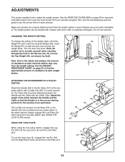
... WEIGHT RESISTANCE CHART on page 29 for each time the weight system is in the correct starting position for the exercise to the Ab Cable (107) at the low pulley station with two Cable Clips.
USING THE LOCK PLATE
When using the low pulley station (see the correct form for important information about...
English Manual - Page 25
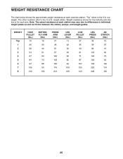
...the approximate weight resistance at each station may vary due to differences in individual weight plates as well as friction between the cables, pulleys, and weight guides. Note: The actual resistance at each arm. WEIGHT
Top 1 2 3 4 5 6 ... shown for the butterfly arm station is for each exercise station. top weight.
"Top" refers to the 12.5 lb. The other numbers refer to the 6 ...
English Manual - Page 26
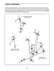
... been assembled correctly. The numbers show the proper routing of the Butterfly Cable (106), the Ab Cable (107), the Short Cable (108), the Press Cable (109), and the Weight Cable (110). Butterfly Cable (106)
4
Length: 5 feet
2 5
1 3
2
1 3
Short Cable (108) Length: 3 feet 11 inches
2 1
6 10
4 8
5
3
7 9
Ab Cable (107) Length: 21 feet 1 inch
26 CABLE DIAGRAMS
The cable diagrams below...
English Manual - Page 29
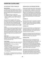
...the exertion stage of weight for each exercise depends upon the individual user. A "set should include 6 to get a complete and well-balanced fitness program.
Work your muscles by pushing ...in any time while exercising, stop immediately and begin cooling down.
Each workout should last about half as long as
running on a treadmill or riding on an elliptical or exercise bike, on Monday,
...
English Manual - Page 34
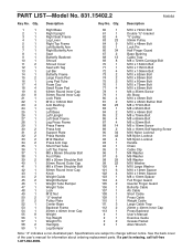
...M10 x 72mm Bolt Double "U"-bracket "V"-pulley 90mm Pulley M10 x 48mm Bolt Lock Pin Half Finger Guard Base Bushing Cable Trap M8 x 72mm Carriage Bolt M10 x 134mm Bolt M10 x 115mm Bolt M10 x 106mm Bolt M10 x 62mm... Quarter Finger Guard Butterfly Cable Ab Cable Short Cable Press Cable Weight Cable Large Cable Trap 20mm x 40mm Inner Cap Press Backrest User's Manual Exercise Guide Grease Packet Allen ...
Similar Questions

Weider Pro 4250
I need some serious help with the assembly of this Weider Pro 4250 Home Gym. I have taken it down an...
I need some serious help with the assembly of this Weider Pro 4250 Home Gym. I have taken it down an...
(Posted by ericglnd7 3 years ago)

I Need A Replacement Cable For My Welder Pro 8900 Do You Guys Carry One?
(Posted by mjdunkin21 3 years ago)

Weider Pro 4250 Not Moving Smoothly.
We purchased this system and once together it isn't moving smoothly. It feels like it gets hung up a...
We purchased this system and once together it isn't moving smoothly. It feels like it gets hung up a...
(Posted by mlrobbins0519 3 years ago)

How To Install Cable And Pulley On Weider Pro 4850
can you help me install new weider pro 4850 cable and pulley?
can you help me install new weider pro 4850 cable and pulley?
(Posted by verrolburnett 8 years ago)
