
English Manual
Page 1
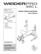
Hoffman Estates, IL 60179 CAUTION Read all precautions and instructions in the space above for future reference. Model No. 831.15928.0 Serial No. Save this equipment. WEIGHT BENCH EXERCISER Userʼs Manual Serial Number Decal (under the seat) • Assembly • Operation • Maintenance • Part List and Drawing Sears, Roebuck and Co. Write the serial number in this manual before using this manual for future reference.
Hoffman Estates, IL 60179 CAUTION Read all precautions and instructions in the space above for future reference. Model No. 831.15928.0 Serial No. Save this equipment. WEIGHT BENCH EXERCISER Userʼs Manual Serial Number Decal (under the seat) • Assembly • Operation • Maintenance • Part List and Drawing Sears, Roebuck and Co. Write the serial number in this manual before using this manual for future reference.
English Manual
Page 2
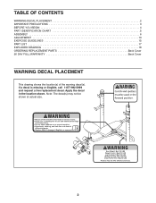
TABLE OF CONTENTS WARNING DECAL PLACEMENT 2 IMPORTANT PRECAUTIONS 3 BEFORE YOU BEGIN 4 PART IDENTIFICATION CHART 5 ASSEMBLY 6 ADJUSTMENT 13 EXERCISE GUIDELINES 15 PART LIST 17 EXPLODED DRAWING 18 ORDERING REPLACEMENT PARTS Back Cover 90 DAY FULL WARRANTY Back Cover WARNING DECAL PLACEMENT This drawing shows the location(s) of the warning decal(s). Note: The decal(s) may not be shown at actual size. 2 Apply the decal in the location shown. If a decal is missing or illegible, call 1-877-992-5999 and request a free replacement decal.
TABLE OF CONTENTS WARNING DECAL PLACEMENT 2 IMPORTANT PRECAUTIONS 3 BEFORE YOU BEGIN 4 PART IDENTIFICATION CHART 5 ASSEMBLY 6 ADJUSTMENT 13 EXERCISE GUIDELINES 15 PART LIST 17 EXPLODED DRAWING 18 ORDERING REPLACEMENT PARTS Back Cover 90 DAY FULL WARRANTY Back Cover WARNING DECAL PLACEMENT This drawing shows the location(s) of the warning decal(s). Note: The decal(s) may not be shown at actual size. 2 Apply the decal in the location shown. If a decal is missing or illegible, call 1-877-992-5999 and request a free replacement decal.
English Manual
Page 4
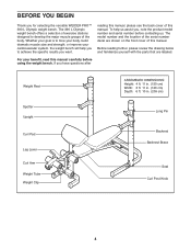
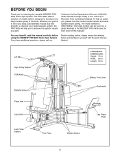
... Tube Weight Clip ASSEMBLED DIMENSIONS: Height: 4 ft. 11 in. (150 cm) Width: 3 ft. 11 in. (120 cm) Depth: 6 ft. 10 in. (209 cm) Long Pin Backrest Backrest Brace Seat Curl Post Knob 4 For your cardiovascular system, the weight bench will help us assist you for selecting the versatile WEIDER PRO™ 390 L Olympic...
... Tube Weight Clip ASSEMBLED DIMENSIONS: Height: 4 ft. 11 in. (150 cm) Width: 3 ft. 11 in. (120 cm) Depth: 6 ft. 10 in. (209 cm) Long Pin Backrest Backrest Brace Seat Curl Post Knob 4 For your cardiovascular system, the weight bench will help us assist you for selecting the versatile WEIDER PRO™ 390 L Olympic...
English Manual
Page 5
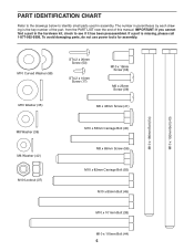
... Carriage Bolt (55) M10 x 85mm Bolt (45) M10 x 101mm Bolt (38) M10 x 110mm Bolt (44) 5 To avoid damaging parts, do not use power tools for assembly. IMPORTANT: If you cannot find a part in the hardware kit, check to identify small parts used in parentheses by each drawing is missing, please call... LIST near the end of this manual. PART IDENTIFICATION CHART Refer to the drawings below to see if it has been preassembled. The number in assembly.
... Carriage Bolt (55) M10 x 85mm Bolt (45) M10 x 101mm Bolt (38) M10 x 110mm Bolt (44) 5 To avoid damaging parts, do not use power tools for assembly. IMPORTANT: If you cannot find a part in the hardware kit, check to identify small parts used in parentheses by each drawing is missing, please call... LIST near the end of this manual. PART IDENTIFICATION CHART Refer to the drawings below to see if it has been preassembled. The number in assembly.

English Manual
Page 6
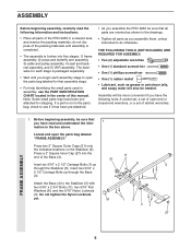
...as you have a socket set, a set of open-end or closed-end wrenches, or a set of ratchet wrenches. 1. ASSEMBLY • Assembly requires two persons. • Because of its size and weight, assemble the weight bench in a cleared area and remove the packing materials. Then, tighten an M8 x 65mm Screw (56) with two... Front Stabilizer (2) with an M8 Washer (36) into the Front Stabilizer (2) and the Front Leg (4). 4 2 Square Holes 37 56 36 55 6 To make assembly easier, read the tips at 1 the top of this page before your begin. Make sure that the square holes are facing the floor.
...as you have a socket set, a set of open-end or closed-end wrenches, or a set of ratchet wrenches. 1. ASSEMBLY • Assembly requires two persons. • Because of its size and weight, assemble the weight bench in a cleared area and remove the packing materials. Then, tighten an M8 x 65mm Screw (56) with two... Front Stabilizer (2) with an M8 Washer (36) into the Front Stabilizer (2) and the Front Leg (4). 4 2 Square Holes 37 56 36 55 6 To make assembly easier, read the tips at 1 the top of this page before your begin. Make sure that the square holes are facing the floor.
English Manual
Page 2
WEIDER is a registered trademark of this manual. TABLE OF CONTENTS IMPORTANT PRECAUTIONS 3 BEFORE YOU BEGIN 4 ASSEMBLY 5 HOW TO USE THE HOME GYM SYSTEM 22 WEIGHT RESISTANCE CHART 24 TROUBLESHOOTING AND MAINTENANCE 25 CABLE DIAGRAMS 26 ORDERING REPLACEMENT PARTS Back Cover LIMITED WARRANTY Back Cover Note: A PART IDENTIFICATION CHART and a PART LIST/EXPLODED DRAWING are attached to the center of ICON Health & Fitness, Inc. 2 Remove the PART IDENTIFICATION CHART and the PART LIST/EXPLODED DRAWING before beginning assembly.
WEIDER is a registered trademark of this manual. TABLE OF CONTENTS IMPORTANT PRECAUTIONS 3 BEFORE YOU BEGIN 4 ASSEMBLY 5 HOW TO USE THE HOME GYM SYSTEM 22 WEIGHT RESISTANCE CHART 24 TROUBLESHOOTING AND MAINTENANCE 25 CABLE DIAGRAMS 26 ORDERING REPLACEMENT PARTS Back Cover LIMITED WARRANTY Back Cover Note: A PART IDENTIFICATION CHART and a PART LIST/EXPLODED DRAWING are attached to the center of ICON Health & Fitness, Inc. 2 Remove the PART IDENTIFICATION CHART and the PART LIST/EXPLODED DRAWING before beginning assembly.
English Manual
Page 4
... model number is to achieve the specific results you , please note the product model number and serial number before using the WEIDER® PRO 9635 Home Gym System. Length: 64 in . Width: 89 in . Military Press Arm Backrests Press Arm Leg Lever Low Pulley...VKR Arms Butterfly Arms ASSEMBLED DIMENSIONS: Height: 76 in. Mountain Time (excluding holidays). Customer Service Department toll-free at 1-800-9993756, Monday through Friday, 6 a.m. For your goal is WESY96352. The PRO 9635 offers a selection of weight stations designed to the WEIDER® PRO 9635 (see the front ...
... model number is to achieve the specific results you , please note the product model number and serial number before using the WEIDER® PRO 9635 Home Gym System. Length: 64 in . Width: 89 in . Military Press Arm Backrests Press Arm Leg Lever Low Pulley...VKR Arms Butterfly Arms ASSEMBLED DIMENSIONS: Height: 76 in. Mountain Time (excluding holidays). Customer Service Department toll-free at 1-800-9993756, Monday through Friday, 6 a.m. For your goal is WESY96352. The PRO 9635 offers a selection of weight stations designed to the WEIDER® PRO 9635 (see the front ...
English Manual
Page 5
...box above. If a part is broken into the end of the Base (4). Assembly will also be more convenient if you assemble them, unless instructed to see if it has been pre-attached. • As you assemble the PRO 9635 be sure that you have read the following tools: A socket set, a set... of open-end or closed-end wrenches, or a set of the PRO 9635 in a cleared area and remove the packing materials; Before beginning assembly, be sure that assembly stage. • For help identifying the small parts used in assembly, use the PART IDENTIFICATION CHART located in the center of the packing ...
...box above. If a part is broken into the end of the Base (4). Assembly will also be more convenient if you assemble them, unless instructed to see if it has been pre-attached. • As you assemble the PRO 9635 be sure that you have read the following tools: A socket set, a set... of open-end or closed-end wrenches, or a set of the PRO 9635 in a cleared area and remove the packing materials; Before beginning assembly, be sure that assembly stage. • For help identifying the small parts used in assembly, use the PART IDENTIFICATION CHART located in the center of the packing ...

English Manual
Page 6
... Bolts (1) in the Stabilizer (5). Do not tighten the Nylon Locknuts yet. 2. The high side of Brackets 56 5 1 1 3. Do not tighten the Nylon Locknuts yet. FRAME ASSEMBLY 4 1 42 6 3 6 Slide the VKR Upright (74) and the Leg Press Upright (56) onto the indicated 5/16" x 2 1/2" Carriage Bolts (1) in the Base (4). 3 Hand-tighten a 5/16" Nylon...
... Bolts (1) in the Stabilizer (5). Do not tighten the Nylon Locknuts yet. 2. The high side of Brackets 56 5 1 1 3. Do not tighten the Nylon Locknuts yet. FRAME ASSEMBLY 4 1 42 6 3 6 Slide the VKR Upright (74) and the Leg Press Upright (56) onto the indicated 5/16" x 2 1/2" Carriage Bolts (1) in the Base (4). 3 Hand-tighten a 5/16" Nylon...

English Manual
Page 7
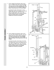
... (56) with two 5/16" x 2 3/4" Bolts (11), two 5/16" Flat Washers (8), and two 5/16" Nylon Locknuts (3). 55 11 49 8 44 3 44 Crossbar 3 56 42 74 FRAME ASSEMBLY 5. Be sure that the pin grooves are all Nylon Locknuts used in the Stabilizer (5). Press a 2" Square Inner Cap (27) into each set of the crossbar...
... (56) with two 5/16" x 2 3/4" Bolts (11), two 5/16" Flat Washers (8), and two 5/16" Nylon Locknuts (3). 55 11 49 8 44 3 44 Crossbar 3 56 42 74 FRAME ASSEMBLY 5. Be sure that the pin grooves are all Nylon Locknuts used in the Stabilizer (5). Press a 2" Square Inner Cap (27) into each set of the crossbar...
English Manual
Page 8
...) into the end of the holes in the Weight Guides are at the top, as shown. 65 Pin 63 62 Lubricate 64 Pin Grooves FRAME ASSEMBLY 25 8. Lubricate the inside of the other Top Weight (65).
...) into the end of the holes in the Weight Guides are at the top, as shown. 65 Pin 63 62 Lubricate 64 Pin Grooves FRAME ASSEMBLY 25 8. Lubricate the inside of the other Top Weight (65).

English Manual
Page 9
... (55) with a 5/16" x 6" Bolt (60), two 1/2" x 3/4" Spacers (61), and a 5/16" Nylon Locknut (3). 9 61 60 73 3 61 60 3 55 62 FRAME ASSEMBLY ARM ASSEMBLY 10. Do not overtighten the Nylon Locknut. Press a 1" x 7/8" Plastic Bushing (90) onto each end of the Stabilizer (5). Make sure that the pulleys are on the...Press Pin (97). 11. Note: This will be on the Press Frame (17). Locate and open the parts bag labeled 10 "ARM ASSEMBLY." The Plastic Bushings should fit on each welded spacer on this side 59-Lubricate 21 Welded Spacers 90 Align the welded tubes on the side...
... (55) with a 5/16" x 6" Bolt (60), two 1/2" x 3/4" Spacers (61), and a 5/16" Nylon Locknut (3). 9 61 60 73 3 61 60 3 55 62 FRAME ASSEMBLY ARM ASSEMBLY 10. Do not overtighten the Nylon Locknut. Press a 1" x 7/8" Plastic Bushing (90) onto each end of the Stabilizer (5). Make sure that the pulleys are on the...Press Pin (97). 11. Note: This will be on the Press Frame (17). Locate and open the parts bag labeled 10 "ARM ASSEMBLY." The Plastic Bushings should fit on each welded spacer on this side 59-Lubricate 21 Welded Spacers 90 Align the welded tubes on the side...
English Manual
Page 10
ARM ASSEMBLY 12. Attach a "V"-Pulley (50) and a Long Cable Trap (31) to confuse the Right Arm with soapy water. Do not tighten the Nylon Locknut yet. 13 ... 44 Axle 69 70 10 Note: Be careful not to the Right Arm (48) with two 5/16" x 2 1/2" Bolts (22) and two 5/16" Nylon Locknuts (3). 22 Assemble the other Press Arm (46) in the same manner. Lubricate both axles on each Arm. Tap two 1" Retainers (69) and a 1" Round Cover Cap (70) onto...
ARM ASSEMBLY 12. Attach a "V"-Pulley (50) and a Long Cable Trap (31) to confuse the Right Arm with soapy water. Do not tighten the Nylon Locknut yet. 13 ... 44 Axle 69 70 10 Note: Be careful not to the Right Arm (48) with two 5/16" x 2 1/2" Bolts (22) and two 5/16" Nylon Locknuts (3). 22 Assemble the other Press Arm (46) in the same manner. Lubricate both axles on each Arm. Tap two 1" Retainers (69) and a 1" Round Cover Cap (70) onto...
English Manual
Page 11
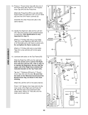
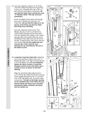
... lengths and ends of each Cable is on pages 26-27 of the Military Press Arm (84). See the inset drawing. IMPORTANT: While assembling the cables, do not overtighten the bolts and nuts attaching the pulleys. Attach the Pulley to turn freely. 17 17. 15. The approximate... the Pivot Arm (101) with a 3/8" x 3 1/4" Bolt (67) and a 3/8" Nylon Locknut (21). 74 32 49 32 84 101 83 67 56 ARM ASSEMBLY CABLE ASSEMBLY 33 101 16. Press two 1" Round Inner Caps (49) into the indicated end of this section, fully unwind the four Cables. Attach the Military 15...
... lengths and ends of each Cable is on pages 26-27 of the Military Press Arm (84). See the inset drawing. IMPORTANT: While assembling the cables, do not overtighten the bolts and nuts attaching the pulleys. Attach the Pulley to turn freely. 17 17. 15. The approximate... the Pivot Arm (101) with a 3/8" x 3 1/4" Bolt (67) and a 3/8" Nylon Locknut (21). 74 32 49 32 84 101 83 67 56 ARM ASSEMBLY CABLE ASSEMBLY 33 101 16. Press two 1" Round Inner Caps (49) into the indicated end of this section, fully unwind the four Cables. Attach the Military 15...
English Manual
Page 12
... the Long Cable Trap (31) is in place. 12 Tighten the 3/8" x 2 1/2" Bolt (86) and the 3/8" Nylon Locknut (not shown). 58 31 86 50 48 CABLE ASSEMBLY 21. the Pulley Bracket must be able to the Top 21 Frame (55) with a 3/8" x 2 1/2" Bolt (86) and a 3/8" Nylon Locknut (21). Tighten the 3/8" x 2" 20 12 Bolt...
... the Long Cable Trap (31) is in place. 12 Tighten the 3/8" x 2 1/2" Bolt (86) and the 3/8" Nylon Locknut (not shown). 58 31 86 50 48 CABLE ASSEMBLY 21. the Pulley Bracket must be able to the Top 21 Frame (55) with a 3/8" x 2 1/2" Bolt (86) and a 3/8" Nylon Locknut (21). Tighten the 3/8" x 2" 20 12 Bolt...
English Manual
Page 13
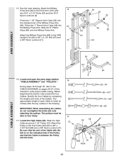
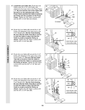
...sure that the Cable and Pulley move smoothly. 22 66 21 57 23 55 58 15 12 57 Bracket 58 15 58 12 15 CABLE ASSEMBLY 21 24. Attach the Pulley to the bracket on the outside of the 3 1/2" Low Pulley (76) for part identification. Note: This... Top Frame (55) with the 5/8" x 9/16" Spacer (7) between the Pulley and the Press Frame (17). Attach a 3 1/2" Pulley (15) and a Cable Trap (66) to complete the assembly of the Pulley and that the 3/8" x 3 3/4" Bolt (88), the 3/8" Flat Washer (9), the 5/8" x 9/16" Spacer (7), the 3 1/2" Low Pulley (76), and the 3/8" Nylon Locknut (21) are oriented...
...sure that the Cable and Pulley move smoothly. 22 66 21 57 23 55 58 15 12 57 Bracket 58 15 58 12 15 CABLE ASSEMBLY 21 24. Attach the Pulley to the bracket on the outside of the 3 1/2" Low Pulley (76) for part identification. Note: This... Top Frame (55) with the 5/8" x 9/16" Spacer (7) between the Pulley and the Press Frame (17). Attach a 3 1/2" Pulley (15) and a Cable Trap (66) to complete the assembly of the Pulley and that the 3/8" x 3 3/4" Bolt (88), the 3/8" Flat Washer (9), the 5/8" x 9/16" Spacer (7), the 3 1/2" Low Pulley (76), and the 3/8" Nylon Locknut (21) are oriented...
English Manual
Page 14
... Inset shows view from other side 23 27. Tighten the 3/8" Nylon Locknut (21) and the 3/8" x 3 1/2" Bolt (not shown). 23 15 21 66 17 28. CABLE ASSEMBLY 25.
... Inset shows view from other side 23 27. Tighten the 3/8" Nylon Locknut (21) and the 3/8" x 3 1/2" Bolt (not shown). 23 15 21 66 17 28. CABLE ASSEMBLY 25.
English Manual
Page 15
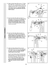
... onto the end of the Cable only a couple of the Low Cable (23) to a Small "U"Bracket (71) with a 1/4" Nylon Locknut (2) 3 and a 1/4" Flat Washer (10). CABLE ASSEMBLY 29. Locate the Military Press Cable (72). Attach the end of turns, as shown in the inset drawing. Attach the High Cable (58) to the...
... onto the end of the Cable only a couple of the Low Cable (23) to a Small "U"Bracket (71) with a 1/4" Nylon Locknut (2) 3 and a 1/4" Flat Washer (10). CABLE ASSEMBLY 29. Locate the Military Press Cable (72). Attach the end of turns, as shown in the inset drawing. Attach the High Cable (58) to the...
English Manual
Page 16
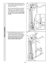
...) and a 3/8" Nylon Locknut (21). Attach the Pulley and a Cable Trap (66) to hold the Cable in place. 33 15 88 66 9 101 72 21 CABLE ASSEMBLY 16 Be sure that the Cable Trap is on the Stabilizer (5) with the 3/8" x 3 3/4" Bolt (88), a 3/8" Flat Washer (9), and a 3/8" Nylon Locknut (21). 32. Wrap the Military...
...) and a 3/8" Nylon Locknut (21). Attach the Pulley and a Cable Trap (66) to hold the Cable in place. 33 15 88 66 9 101 72 21 CABLE ASSEMBLY 16 Be sure that the Cable Trap is on the Stabilizer (5) with the 3/8" x 3 3/4" Bolt (88), a 3/8" Flat Washer (9), and a 3/8" Nylon Locknut (21). 32. Wrap the Military...
English Manual
Page 17
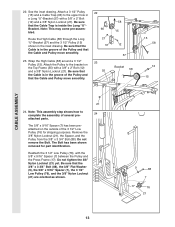
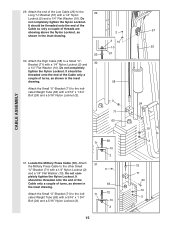
... a 3 1/2" Pulley (15). See inset drawing B. Be sure that the Cable and Pulley move smoothly and that the Cable is in the groove of the Pulley. assembled.) Route the Military Press Cable (72) through the Pivot Arm (101) from the indicated side. Attach the 35 end of the Bolt. The ball on... move smoothly. Attach a 3 1/2" Pulley 34 (15) and a Cable Trap (66) to pivot. 15 57 72 21 57 11 8 15 A 66 12 B 101 93 72 CABLE ASSEMBLY 35. Do not completely tighten the Nylon Locknut. See inset drawing A. Locate the Leg Press Cable (99). Tighten a 5/16" Nylon Jam Nut (93) onto the...
... a 3 1/2" Pulley (15). See inset drawing B. Be sure that the Cable and Pulley move smoothly and that the Cable is in the groove of the Pulley. assembled.) Route the Military Press Cable (72) through the Pivot Arm (101) from the indicated side. Attach the 35 end of the Bolt. The ball on... move smoothly. Attach a 3 1/2" Pulley 34 (15) and a Cable Trap (66) to pivot. 15 57 72 21 57 11 8 15 A 66 12 B 101 93 72 CABLE ASSEMBLY 35. Do not completely tighten the Nylon Locknut. See inset drawing A. Locate the Leg Press Cable (99). Tighten a 5/16" Nylon Jam Nut (93) onto the...


