
English Manual
Page 11
...Inner Caps (32) into 21 the Military Press Arm. IMPORTANT: While assembling the cables, do not overtighten the bolts and nuts attaching the pulleys. Attach the Military Press Arm (84) to verify proper cable routing. Press two 1" Round Inner Caps (49) into the indicated end of this section..., fully unwind the four Cables. Attach the Pulley to the CABLE DIAGRAMS on the indicated side of the Pulley and that the...
...Inner Caps (32) into 21 the Military Press Arm. IMPORTANT: While assembling the cables, do not overtighten the bolts and nuts attaching the pulleys. Attach the Military Press Arm (84) to verify proper cable routing. Press two 1" Round Inner Caps (49) into the indicated end of this section..., fully unwind the four Cables. Attach the Pulley to the CABLE DIAGRAMS on the indicated side of the Pulley and that the...
English Manual
Page 12
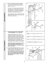
... Tighten the 3/8" x 2 1/2" Bolt (86) and the 3/8" Nylon Locknut (not shown). 86 31 58 50 Bracket 42 21 86 31 50 58 47 20. Route the High Cable 55 66 (58) around the "V"Pulley (50) on the Front Upright (42) with the 5/16" x 5" Bolt (68) and a 68 5/16" Nylon ... with a 3/8" x 2 1/2" Bolt (86) and a 3/8" Nylon Locknut (21). See the inset drawing. Route the High Cable (58) around a "V"-Pulley 18 (50). Pulley and that the Long Cable Trap (31) is in place. Wrap the High Cable (58) around the "V"- 20 Pulley (50) on the Right Arm (48). the Pulley Bracket must...
... Tighten the 3/8" x 2 1/2" Bolt (86) and the 3/8" Nylon Locknut (not shown). 86 31 58 50 Bracket 42 21 86 31 50 58 47 20. Route the High Cable 55 66 (58) around the "V"Pulley (50) on the Front Upright (42) with the 5/16" x 5" Bolt (68) and a 68 5/16" Nylon ... with a 3/8" x 2 1/2" Bolt (86) and a 3/8" Nylon Locknut (21). See the inset drawing. Route the High Cable (58) around a "V"-Pulley 18 (50). Pulley and that the Long Cable Trap (31) is in place. Wrap the High Cable (58) around the "V"- 20 Pulley (50) on the Right Arm (48). the Pulley Bracket must...
English Manual
Page 13
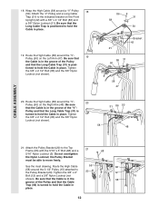
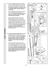
... 24. Remove the 3/8" Nylon Locknut (21), the Spacer, and the Pulley from the 3/8" x 3 3/4" Bolt (88). Be sure that the Cable is in the groove of the 3 1/2" Low Pulley (76) for part identification. Do not tighten the 3/8" Nylon Locknut (21) yet. Be ... Flat Washer (9), the 5/8" x 9/16" Spacer (7), the 3 1/2" Low Pulley (76), and the 3/8" Nylon Locknut (21) are oriented as shown. 13 9 88 7 17 76 21 Route the High Cable (58) through the Long "U"-Bracket (57) and the 3 1/2" Pulley (15) shown in a Long "U"-Bracket (57) with a 3/8" x 2" Bolt (12) and a 3/8" Nylon Locknut...
... 24. Remove the 3/8" Nylon Locknut (21), the Spacer, and the Pulley from the 3/8" x 3 3/4" Bolt (88). Be sure that the Cable is in the groove of the 3 1/2" Low Pulley (76) for part identification. Do not tighten the 3/8" Nylon Locknut (21) yet. Be ... Flat Washer (9), the 5/8" x 9/16" Spacer (7), the 3 1/2" Low Pulley (76), and the 3/8" Nylon Locknut (21) are oriented as shown. 13 9 88 7 17 76 21 Route the High Cable (58) through the Long "U"-Bracket (57) and the 3 1/2" Pulley (15) shown in a Long "U"-Bracket (57) with a 3/8" x 2" Bolt (12) and a 3/8" Nylon Locknut...
English Manual
Page 14
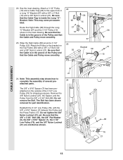
... x 3 3/4" Bolt (88). 23 15 88 66 42 Inset shows view from other side 14 Route the Low Cable (23) around the Pulley as shown. See the inset drawing. 23 Be sure that the Cable Trap (66) is routed around the 3 1/2" Pulley (15) attached to the lower hole in the Front Upright (42). See...66 17 28. Locate the Low Cable (23). Route the Low Cable (23) around the 3 1/2" 28 Pulley (15) attached to hold the Cable in place and that the 15 42 Cable is routed around the Pulley as shown. Be sure that the Cable Trap (66) is turned to hold the Cable in the Press Frame (17). ...
... x 3 3/4" Bolt (88). 23 15 88 66 42 Inset shows view from other side 14 Route the Low Cable (23) around the Pulley as shown. See the inset drawing. 23 Be sure that the Cable Trap (66) is routed around the 3 1/2" Pulley (15) attached to the lower hole in the Front Upright (42). See...66 17 28. Locate the Low Cable (23). Route the Low Cable (23) around the 3 1/2" 28 Pulley (15) attached to hold the Cable in place and that the 15 42 Cable is routed around the Pulley as shown. Be sure that the Cable Trap (66) is turned to hold the Cable in the Press Frame (17). ...
English Manual
Page 17
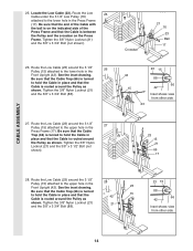
... Route the Military Press Cable (72) through the Pivot Arm (101) from the indicated side. There must be threaded onto the end of the Cable only a couple of the Cable to the Long "U"- Locate the Leg Press Cable (99). It should be on the indicated side of the Pulley and that the Cable ...not fully tighten the second Jam Nut. Attach the Pulley to the upper hole in the groove of the Pulley. Attach a 3 1/2" Pulley 34 (15) and a Cable Trap (66) to the Leg Press Upright (56) with a 1/4" Nylon Locknut (2) and a 1/4" Flat Washer (10). Thread another 5/16" Nylon Jam Nut onto ...
... Route the Military Press Cable (72) through the Pivot Arm (101) from the indicated side. There must be threaded onto the end of the Cable only a couple of the Cable to the Long "U"- Locate the Leg Press Cable (99). It should be on the indicated side of the Pulley and that the Cable ...not fully tighten the second Jam Nut. Attach the Pulley to the upper hole in the groove of the Pulley. Attach a 3 1/2" Pulley 34 (15) and a Cable Trap (66) to the Leg Press Upright (56) with a 1/4" Nylon Locknut (2) and a 1/4" Flat Washer (10). Thread another 5/16" Nylon Jam Nut onto ...
English Manual
Page 21
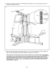
Before using the home gym system, pull each cable a few times to the Front Upright (42) under the "WEIDER" nameplate as shown. 46 WEIDER Nameplate 42 PRO 9635 Decal 47. IMPORTANT: If the cables are not properly installed, they may be sure that all parts have been properly tightened. If there is... page 22 of this manual for proper cable routing. Make sure that the cables move smoothly, find and correct the problem. See the CABLE DIAGRAMS on page 25. 21 Remove the adhesive backing from the PRO 9635 decal and apply it by tightening the cables. If one of this manual. See ...
Before using the home gym system, pull each cable a few times to the Front Upright (42) under the "WEIDER" nameplate as shown. 46 WEIDER Nameplate 42 PRO 9635 Decal 47. IMPORTANT: If the cables are not properly installed, they may be sure that all parts have been properly tightened. If there is... page 22 of this manual for proper cable routing. Make sure that the cables move smoothly, find and correct the problem. See the CABLE DIAGRAMS on page 25. 21 Remove the adhesive backing from the PRO 9635 decal and apply it by tightening the cables. If one of this manual. See ...
English Manual
Page 26
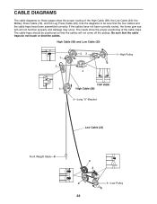
... Weight Stack-8 4 3 2 1-Low Pulley 26 The insets show the proper routing of the cable traps. Be sure that the cables will not function properly and damage may occur. The cable traps should be sure that the four cables and the cable traps have not been correctly routed, the home gym system will not come off the pulleys...
... Weight Stack-8 4 3 2 1-Low Pulley 26 The insets show the proper routing of the cable traps. Be sure that the cables will not function properly and damage may occur. The cable traps should be sure that the four cables and the cable traps have not been correctly routed, the home gym system will not come off the pulleys...


