
English Manual
Page 3
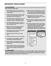
... weight of 300 pounds. Keep hands and fingers clear of this product. 3 The weights will fall with pre-existing health problems. Read all of the pulleys. 13. ICON assumes no responsibility for foot protection. 9. It is designed to ensure that the cables remain on the... pulleys at all instructions in any time while exercising, stop immediately and make sure that the cables are raised. Do not use the lat bar. 14. ...
... weight of 300 pounds. Keep hands and fingers clear of this product. 3 The weights will fall with pre-existing health problems. Read all of the pulleys. 13. ICON assumes no responsibility for foot protection. 9. It is designed to ensure that the cables remain on the... pulleys at all instructions in any time while exercising, stop immediately and make sure that the cables are raised. Do not use the lat bar. 14. ...
English Manual
Page 4
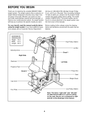
... (see the front cover of the body. Butterfly Arms Right Side Backrest Preacher Pad Decal 2 Leg Lever High Pulley Station Decal 1 Lat Bar Left Side Press Arm Seat Weight Stack Foot Plate Low Pulley Station Note: The terms "right side" and "left on the seat; The weight system offers a selection of weight... on the drawings in . Length: 44 in the manual. 4 For your cardiovascular system, the weight system will help us assist you for selecting the versatile WEIDER® 8525 weight system. toll-free at 1-800-999-3756, Monday through Friday, 6 a.m.
... (see the front cover of the body. Butterfly Arms Right Side Backrest Preacher Pad Decal 2 Leg Lever High Pulley Station Decal 1 Lat Bar Left Side Press Arm Seat Weight Stack Foot Plate Low Pulley Station Note: The terms "right side" and "left on the seat; The weight system offers a selection of weight... on the drawings in . Length: 44 in the manual. 4 For your cardiovascular system, the weight system will help us assist you for selecting the versatile WEIDER® 8525 weight system. toll-free at 1-800-999-3756, Monday through Friday, 6 a.m.
English Manual
Page 8
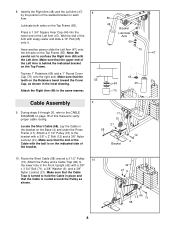
...sure that the end of the Cable with the ball is routed around a 3 1/2" Pulley 10 (15). Make sure that the teeth on the Top Frame (55). Make sure... refer to hold the Cable in the same manner. 70 Cable Assembly 9. Route the Short Cable (58) around the Pulley as shown in the inset drawing. 44 69 45 Attach the Right Arm (48) in place and that the upper end...the position of the welded bracket on page 18 of the Left Arm (47). Locate the Short Cable (58). Attach a 3 1/2" Pulley (15) to confuse the Right Arm (48) with soapy water and slide a 10" Pad (45) onto it. 55 48 ...
...sure that the end of the Cable with the ball is routed around a 3 1/2" Pulley 10 (15). Make sure that the teeth on the Top Frame (55). Make sure... refer to hold the Cable in the same manner. 70 Cable Assembly 9. Route the Short Cable (58) around the Pulley as shown in the inset drawing. 44 69 45 Attach the Right Arm (48) in place and that the upper end...the position of the welded bracket on page 18 of the Left Arm (47). Locate the Short Cable (58). Attach a 3 1/2" Pulley (15) to confuse the Right Arm (48) with soapy water and slide a 10" Pad (45) onto it. 55 48 ...
English Manual
Page 9
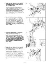
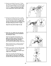
... that the Cable Trap (66) is turned to hold the Cable in this step has been preassembled. Route the Short Cable (58) around the Pulley as shown. it should be threaded onto the end of the Cable so only a couple of the Short Cable (58) to the upper hole ...in place and that the end of the Cable with the ball is routed around the 3 1/2" 12 Pulley (15). Locate the Long Cable (23). It is shown exploded in this drawing for clarity. Attach the Pulley and a Cable Trap (66) to the Long "U"-bracket (57) with a 3/8" x 3 3/4" Bolt (71), a 3/8" Washer (9), and a 3/8"...
... that the Cable Trap (66) is turned to hold the Cable in this step has been preassembled. Route the Short Cable (58) around the Pulley as shown. it should be threaded onto the end of the Cable so only a couple of the Short Cable (58) to the upper hole ...in place and that the end of the Cable with the ball is routed around the 3 1/2" 12 Pulley (15). Locate the Long Cable (23). It is shown exploded in this drawing for clarity. Attach the Pulley and a Cable Trap (66) to the Long "U"-bracket (57) with a 3/8" x 3 3/4" Bolt (71), a 3/8" Washer (9), and a 3/8"...
English Manual
Page 10
... sure that the Cable is in place. Make sure that the Cable Trap (66) is positioned to hold the Cable in the groove of the Pulley and that the Long Cable Trap is turned to the indicated bracket on the Front Upright (42) with the Right Arm (48). 16 48 47... this drawing for clarity. Tighten the 3/8" x 2" Bolt (12) and the 3/8" Nylon Locknut (21). Make sure that the Long Cable Trap is inside of the "V"-pulley. Attach the "V"-Pulley and a Long Cable Trap (50) to hold the Cable in the groove of the "U"-bracket. Make sure that the Cable Trap is positioned to...
... sure that the Cable is in place. Make sure that the Cable Trap (66) is positioned to hold the Cable in the groove of the Pulley and that the Long Cable Trap is turned to the indicated bracket on the Front Upright (42) with the Right Arm (48). 16 48 47... this drawing for clarity. Tighten the 3/8" x 2" Bolt (12) and the 3/8" Nylon Locknut (21). Make sure that the Long Cable Trap is inside of the "V"-pulley. Attach the "V"-Pulley and a Long Cable Trap (50) to hold the Cable in the groove of the "U"-bracket. Make sure that the Cable Trap is positioned to...
English Manual
Page 11
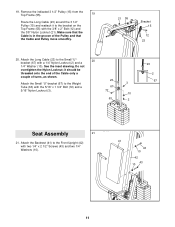
... (41) to the Small "U"- 20 bracket (67) with the 3/8" x 2" Bolt (12) and the 3/8" Nylon Locknut (21). Remove the indicated 3 1/2" Pulley (15) from the Top Frame (55). 19 Route the Long Cable (23) around the 3 1/2" Pulley (15) and reattach it should be threaded onto the end of the Cable only a couple of the...
... (41) to the Small "U"- 20 bracket (67) with the 3/8" x 2" Bolt (12) and the 3/8" Nylon Locknut (21). Remove the indicated 3 1/2" Pulley (15) from the Top Frame (55). 19 Route the Long Cable (23) around the 3 1/2" Pulley (15) and reattach it should be threaded onto the end of the Cable only a couple of the...
English Manual
Page 13
... (77) with two 1/4" x 3/4" Screws (18). 56 77 18 27. see TROUBLESHOOTING AND MAINTENANCE on page 18 of the cables does not move smoothly over the pulleys. IMPORTANT: If the cables are not properly installed, they may be explained in the cables, you will be damaged when heavy weight is any slack...
... (77) with two 1/4" x 3/4" Screws (18). 56 77 18 27. see TROUBLESHOOTING AND MAINTENANCE on page 18 of the cables does not move smoothly over the pulleys. IMPORTANT: If the cables are not properly installed, they may be explained in the cables, you will be damaged when heavy weight is any slack...
English Manual
Page 14
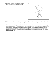
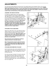
... the correct starting position for each exercise. Next, remove the Seat Knob (40) and the 5/16" x 2 3/4" Carriage Bolt (14) from 6.5 pounds to the cables and pulleys, the actual amount of resistance at each weight station. 25 26 ATTACHING THE ACCESSORIES Attach the Lat Bar (54) to be performed. Refer to the...
... the correct starting position for each exercise. Next, remove the Seat Knob (40) and the 5/16" x 2 3/4" Carriage Bolt (14) from 6.5 pounds to the cables and pulleys, the actual amount of resistance at each weight station. 25 26 ATTACHING THE ACCESSORIES Attach the Lat Bar (54) to be performed. Refer to the...
English Manual
Page 15
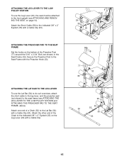
ATTACHING THE LEG LEVER TO THE LOW PULLEY STATION To use the Lat Bar (54) to do curl exercises, attach the short cable to the leg lever, and the preacher pad (not shown) ... LEG LEVER To use the Leg Lever (29), the seat must be attached to the front upright (see ATTACHING THE LEG LEVER TO THE LOW PULLEY STATION and ATTACHING THE PREACHER PAD TO THE SEAT FRAME, above). Attach one end of a Chain (52) to the indicated 3/8" x 2" Eyebolt (35) on page 14...
ATTACHING THE LEG LEVER TO THE LOW PULLEY STATION To use the Lat Bar (54) to do curl exercises, attach the short cable to the leg lever, and the preacher pad (not shown) ... LEG LEVER To use the Leg Lever (29), the seat must be attached to the front upright (see ATTACHING THE LEG LEVER TO THE LOW PULLEY STATION and ATTACHING THE PREACHER PAD TO THE SEAT FRAME, above). Attach one end of a Chain (52) to the indicated 3/8" x 2" Eyebolt (35) on page 14...
English Manual
Page 16
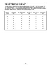
... other numbers refer to the 6.5 lb. top weight. "Top" refers to the 12.5 lb. WEIGHT PLATES PRESS ARM (lbs.) BUTTERFLY ARM (lbs.) LEG LEVER HIGH PULLEY LOW PULLEY (lbs.) (lbs.) (lbs.) Top 20 1 45 2 70 3 99 4 128 5 153 6 184 10 15 14 24 22 36 28 54 33 54 44 82 42... shows the approximate weight resistance at each weight station may vary due to differences in individual weight plates, as well as friction between the cables, pulleys, and weight guides.
... other numbers refer to the 6.5 lb. top weight. "Top" refers to the 12.5 lb. WEIGHT PLATES PRESS ARM (lbs.) BUTTERFLY ARM (lbs.) LEG LEVER HIGH PULLEY LOW PULLEY (lbs.) (lbs.) (lbs.) Top 20 1 45 2 70 3 99 4 128 5 153 6 184 10 15 14 24 22 36 28 54 33 54 44 82 42... shows the approximate weight resistance at each weight station may vary due to differences in individual weight plates, as well as friction between the cables, pulleys, and weight guides.
English Manual
Page 17
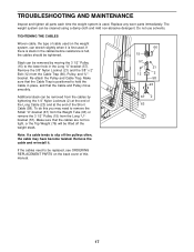
... Remove the 3/8" Nylon Locknut (21) and the 3/8" x 2" Bolt (12) from the Long "U"bracket (57). Additional slack can be removed from the cables by moving the 3 1/2" Pulley (15) to the lower hole in the Long "U"-bracket (57). TROUBLESHOOTING AND MAINTENANCE Inspect and tighten all parts each time the weight system is felt... of the Long Cable (23) and at the end of cable used on the back cover of this you may need to slip off the pulleys often, the cable may have become twisted. If the cables need to be lifted off the weight stack. 15 57 12 66 21 2 58 23...
... Remove the 3/8" Nylon Locknut (21) and the 3/8" x 2" Bolt (12) from the Long "U"bracket (57). Additional slack can be removed from the cables by moving the 3 1/2" Pulley (15) to the lower hole in the Long "U"-bracket (57). TROUBLESHOOTING AND MAINTENANCE Inspect and tighten all parts each time the weight system is felt... of the Long Cable (23) and at the end of cable used on the back cover of this you may need to slip off the pulleys often, the cable may have become twisted. If the cables need to be lifted off the weight stack. 15 57 12 66 21 2 58 23...
English Manual
Page 18
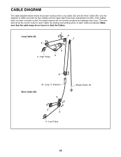
... cable traps have not been correctly routed, the weight system will not function properly and damage may occur. Long Cable (23) 4 5 7 2 3 1-High Pulley 6 5-Long "U"-Bracket Short Cable (58) 4 3 2 1-Low Pulley Weight Stack-8 18 If the Cables have been assembled correctly. Use the diagram to make sure that the cable traps do not...
... cable traps have not been correctly routed, the weight system will not function properly and damage may occur. Long Cable (23) 4 5 7 2 3 1-High Pulley 6 5-Long "U"-Bracket Short Cable (58) 4 3 2 1-Low Pulley Weight Stack-8 18 If the Cables have been assembled correctly. Use the diagram to make sure that the cable traps do not...
English Manual
Page 21
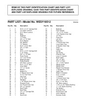
... 2 36 1 37 1 38 1 39 1 40 1 Description 5/16" x 2 1/2" Carriage Bolt 1/4" Nylon Locknut 5/16" Nylon Locknut Base Stabilizer "V"-Pulley 3/8" x 2 1/2" Bolt 5/16" Washer 3/8" Washer 1/4" Washer 5/16" x 2 3/4" Bolt 3/8" x 2" Bolt Seat 5/16" x 2 3/4" Carriage Bolt 3 1/2" Pulley 3/8" x 3 1/2" Bolt Press Frame 1/4" x 3/4" Screw Weight Bumper Pulley Bracket 3/8" Nylon Locknut 5/16" x 2 1/2" Bolt Long Cable 1/4" x 2" Screw Weight Weight Pin 2" Square Inner Cap 12 1/2" Pad...
... 2 36 1 37 1 38 1 39 1 40 1 Description 5/16" x 2 1/2" Carriage Bolt 1/4" Nylon Locknut 5/16" Nylon Locknut Base Stabilizer "V"-Pulley 3/8" x 2 1/2" Bolt 5/16" Washer 3/8" Washer 1/4" Washer 5/16" x 2 3/4" Bolt 3/8" x 2" Bolt Seat 5/16" x 2 3/4" Carriage Bolt 3 1/2" Pulley 3/8" x 3 1/2" Bolt Press Frame 1/4" x 3/4" Screw Weight Bumper Pulley Bracket 3/8" Nylon Locknut 5/16" x 2 1/2" Bolt Long Cable 1/4" x 2" Screw Weight Weight Pin 2" Square Inner Cap 12 1/2" Pad...


