
English Manual
Page 3
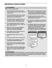
...WARNING: To reduce the risk of all precautions. 3. It is the responsibility of the owner to tip. 11. Use the weight system only on the pulleys at all of 300 pounds. Make sure that all users of the weight system are on all times. 7. Always stand on page 4. Do not use... parts immediately. 12. Keep hands and fingers clear of this area. Cover the floor beneath the weight system to support a maximum user weight of the pulleys. 13. If you feel pain or dizziness at 1-800-999-3756 and order a free replacement decal. Always wear athletic shoes for home use only. ...
...WARNING: To reduce the risk of all precautions. 3. It is the responsibility of the owner to tip. 11. Use the weight system only on the pulleys at all of 300 pounds. Make sure that all users of the weight system are on all times. 7. Always stand on page 4. Do not use... parts immediately. 12. Keep hands and fingers clear of this area. Cover the floor beneath the weight system to support a maximum user weight of the pulleys. 13. If you feel pain or dizziness at 1-800-999-3756 and order a free replacement decal. Always wear athletic shoes for home use only. ...
English Manual
Page 4
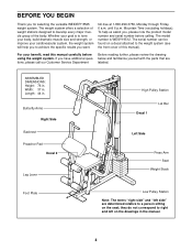
... specific results you to develop every major muscle group of this manual carefully before calling. If you for selecting the versatile WEIDER® 8525 weight system. The serial number can be found on a decal attached to a person sitting on the drawings in . ...Length: 44 in the manual. 4 Butterfly Arms Right Side Backrest Preacher Pad Decal 2 Leg Lever High Pulley Station Decal 1 Lat Bar Left Side Press Arm Seat Weight Stack Foot Plate Low Pulley...
... specific results you to develop every major muscle group of this manual carefully before calling. If you for selecting the versatile WEIDER® 8525 weight system. The serial number can be found on a decal attached to a person sitting on the drawings in . ...Length: 44 in the manual. 4 Butterfly Arms Right Side Backrest Preacher Pad Decal 2 Leg Lever High Pulley Station Decal 1 Lat Bar Left Side Press Arm Seat Weight Stack Foot Plate Low Pulley...
English Manual
Page 8
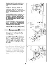
... confuse the Right Arm (48) with a 3/8" x 2" Bolt (12) and a 3/8" Nylon Locknut (21). During steps 9 through 20, refer to the bracket with the Left Arm. Attach a 3 1/2" Pulley (15) to the CABLE DIAGRAM on the Base (4) and under the Press Frame (17). Make sure that the Cable Trap is routed around... a 3 1/2" Pulley 10 (15). Wet the end of the Arm with the ball is behind the indicated bracket on the indicated side of the Cable with soapy ...
... confuse the Right Arm (48) with a 3/8" x 2" Bolt (12) and a 3/8" Nylon Locknut (21). During steps 9 through 20, refer to the bracket with the Left Arm. Attach a 3 1/2" Pulley (15) to the CABLE DIAGRAM on the Base (4) and under the Press Frame (17). Make sure that the Cable Trap is routed around... a 3 1/2" Pulley 10 (15). Wet the end of the Arm with the ball is behind the indicated bracket on the indicated side of the Cable with soapy ...
English Manual
Page 9
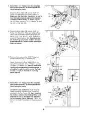
... to the upper hole in this step has been preassembled. Route the Short Cable (58) around the indicated 3 1/2" Pulley (15) attached to the Press Frame (17). Route the Short Cable (58) around the Pulley as shown. Attach the end of the Cable with the ball is turned to the Long "U"-bracket (57... that the end of the Short Cable (58) to hold the Cable in this drawing for clarity. It is routed around the 3 1/2" 12 Pulley (15). Attach the Pulley and a Cable Trap (66) to hold the Cable in place and that the Cable Trap is on the indicated side of threads are showing...
... to the upper hole in this step has been preassembled. Route the Short Cable (58) around the indicated 3 1/2" Pulley (15) attached to the Press Frame (17). Route the Short Cable (58) around the Pulley as shown. Attach the end of the Cable with the ball is turned to the Long "U"-bracket (57... that the end of the Short Cable (58) to hold the Cable in this drawing for clarity. It is routed around the 3 1/2" 12 Pulley (15). Attach the Pulley and a Cable Trap (66) to hold the Cable in place and that the Cable Trap is on the indicated side of threads are showing...
English Manual
Page 10
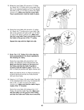
... a Long Cable Trap (50) to the indicated hole in the Long "U"-bracket (57) with a 3/8" x 2 1/2" Bolt (7) and a 3/8" Nylon Locknut (21). Make sure that the Pulley Bracket (20) can move smoothly. 21 20 23 66 15 12 15 12 23 66 21 57 10 It is in place. 23 42 6 7 50 ...21 16. Note: The 3 1/2" Pulley (15) in this drawing for clarity. Make sure that the Cable Trap is positioned to hold the Cable in the groove of the...
... a Long Cable Trap (50) to the indicated hole in the Long "U"-bracket (57) with a 3/8" x 2 1/2" Bolt (7) and a 3/8" Nylon Locknut (21). Make sure that the Pulley Bracket (20) can move smoothly. 21 20 23 66 15 12 15 12 23 66 21 57 10 It is in place. 23 42 6 7 50 ...21 16. Note: The 3 1/2" Pulley (15) in this drawing for clarity. Make sure that the Cable Trap is positioned to hold the Cable in the groove of the...
English Manual
Page 11
...) and reattach it should be threaded onto the end of the Cable only a couple of the Pulley and that the Cable and Pulley move smoothly. 21 55 Bracket 15 12 23 20. Make sure that the Cable is in the groove of turns, as shown. 23 Attach the ...
...) and reattach it should be threaded onto the end of the Cable only a couple of the Pulley and that the Cable and Pulley move smoothly. 21 55 Bracket 15 12 23 20. Make sure that the Cable is in the groove of turns, as shown. 23 Attach the ...
English Manual
Page 13
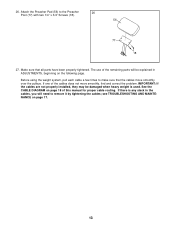
... on the following page. If there is used. 26. see TROUBLESHOOTING AND MAINTENANCE on page 18 of the cables does not move smoothly over the pulleys. Attach the Preacher Pad (56) to make sure that all parts have been properly tightened. If one of this manual for proper cable routing. IMPORTANT...
... on the following page. If there is used. 26. see TROUBLESHOOTING AND MAINTENANCE on page 18 of the cables does not move smoothly over the pulleys. Attach the Preacher Pad (56) to make sure that all parts have been properly tightened. If one of this manual for proper cable routing. IMPORTANT...
English Manual
Page 14
...) to the Long Cable (23) with a Cable Clip (53). The weight setting of the weight stack can be performed. Note: Due to the cables and pulleys, the actual amount of the weight stack, insert the Weight Pin (26) under the desired Weight (25). Adjust the length of the Chain between the...
...) to the Long Cable (23) with a Cable Clip (53). The weight setting of the weight stack can be performed. Note: Due to the cables and pulleys, the actual amount of the weight stack, insert the Weight Pin (26) under the desired Weight (25). Adjust the length of the Chain between the...
English Manual
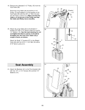
Page 15
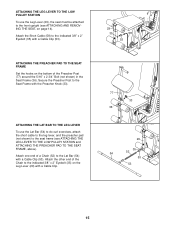
... LEG LEVER To use the Leg Lever (29), the seat must be attached to the front upright (see ATTACHING THE LEG LEVER TO THE LOW PULLEY STATION and ATTACHING THE PREACHER PAD TO THE SEAT FRAME, above). Attach the other end of the Chain to the indicated 3/8" x 2" Eyebolt (35) on the... bottom of a Chain (52) to the indicated 3/8" x 2" Eyebolt (35) with a Cable Clip (53). ATTACHING THE LEG LEVER TO THE LOW PULLEY STATION To use the Lat Bar (54) to do curl exercises, attach the short cable to the leg lever, and the preacher pad (not shown...
... LEG LEVER To use the Leg Lever (29), the seat must be attached to the front upright (see ATTACHING THE LEG LEVER TO THE LOW PULLEY STATION and ATTACHING THE PREACHER PAD TO THE SEAT FRAME, above). Attach the other end of the Chain to the indicated 3/8" x 2" Eyebolt (35) on the... bottom of a Chain (52) to the indicated 3/8" x 2" Eyebolt (35) with a Cable Clip (53). ATTACHING THE LEG LEVER TO THE LOW PULLEY STATION To use the Lat Bar (54) to do curl exercises, attach the short cable to the leg lever, and the preacher pad (not shown...
English Manual
Page 16
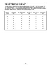
...the approximate weight resistance at each weight station may vary due to differences in individual weight plates, as well as friction between the cables, pulleys, and weight guides. weight plates. Weight resistance shown for the butterfly arm station is for each station. Note: The actual resistance at ...each butterfly arm. "Top" refers to the 12.5 lb. top weight. WEIGHT PLATES PRESS ARM (lbs.) BUTTERFLY ARM (lbs.) LEG LEVER HIGH PULLEY LOW PULLEY (lbs.) (lbs.) (lbs.) Top 20 1 45 2 70 3 99 4 128 5 153 6 184 10 15 14 24 22 36 28 54 33 ...
...the approximate weight resistance at each weight station may vary due to differences in individual weight plates, as well as friction between the cables, pulleys, and weight guides. weight plates. Weight resistance shown for the butterfly arm station is for each station. Note: The actual resistance at ...each butterfly arm. "Top" refers to the 12.5 lb. top weight. WEIGHT PLATES PRESS ARM (lbs.) BUTTERFLY ARM (lbs.) LEG LEVER HIGH PULLEY LOW PULLEY (lbs.) (lbs.) (lbs.) Top 20 1 45 2 70 3 99 4 128 5 153 6 184 10 15 14 24 22 36 28 54 33 ...
English Manual
Page 17
... 3/8" Nylon Locknut (21) and the 3/8" x 2" Bolt (12) from the cables by moving the 3 1/2" Pulley (15) to hold the Cable in the cables before resistance is first used . Re-attach the Pulley and Cable Trap. If the cables need to be removed by tightening the 1/4" Nylon Locknuts (2) at the...it . Make sure that the Cable Trap is used . Additional slack can be removed from the Cable Trap (66), Pulley, and "U"bracket. Make sure that the Cable and Pulley move smoothly. Replace any worn parts immediately. The weight system can be cleaned using a damp cloth and mild non-...
... 3/8" Nylon Locknut (21) and the 3/8" x 2" Bolt (12) from the cables by moving the 3 1/2" Pulley (15) to hold the Cable in the cables before resistance is first used . Re-attach the Pulley and Cable Trap. If the cables need to be removed by tightening the 1/4" Nylon Locknuts (2) at the...it . Make sure that the Cable Trap is used . Additional slack can be removed from the Cable Trap (66), Pulley, and "U"bracket. Make sure that the Cable and Pulley move smoothly. Replace any worn parts immediately. The weight system can be cleaned using a damp cloth and mild non-...
English Manual
Page 18
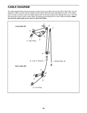
... that the cable traps do not touch or bind the Cables. If the Cables have been assembled correctly. Long Cable (23) 4 5 7 2 3 1-High Pulley 6 5-Long "U"-Bracket Short Cable (58) 4 3 2 1-Low Pulley Weight Stack-8 18 Make sure that the two Cables and the cable traps have not been correctly routed, the weight system will...
... that the cable traps do not touch or bind the Cables. If the Cables have been assembled correctly. Long Cable (23) 4 5 7 2 3 1-High Pulley 6 5-Long "U"-Bracket Short Cable (58) 4 3 2 1-Low Pulley Weight Stack-8 18 Make sure that the two Cables and the cable traps have not been correctly routed, the weight system will...
English Manual
Page 21
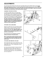
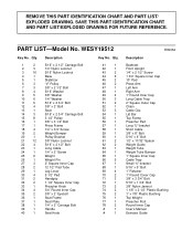
... 2 36 1 37 1 38 1 39 1 40 1 Description 5/16" x 2 1/2" Carriage Bolt 1/4" Nylon Locknut 5/16" Nylon Locknut Base Stabilizer "V"-Pulley 3/8" x 2 1/2" Bolt 5/16" Washer 3/8" Washer 1/4" Washer 5/16" x 2 3/4" Bolt 3/8" x 2" Bolt Seat 5/16" x 2 3/4" Carriage Bolt 3 1/2" Pulley 3/8" x 3 1/2" Bolt Press Frame 1/4" x 3/4" Screw Weight Bumper Pulley Bracket 3/8" Nylon Locknut 5/16" x 2 1/2" Bolt Long Cable 1/4" x 2" Screw Weight Weight Pin 2" Square Inner Cap 12 1/2" Pad...
... 2 36 1 37 1 38 1 39 1 40 1 Description 5/16" x 2 1/2" Carriage Bolt 1/4" Nylon Locknut 5/16" Nylon Locknut Base Stabilizer "V"-Pulley 3/8" x 2 1/2" Bolt 5/16" Washer 3/8" Washer 1/4" Washer 5/16" x 2 3/4" Bolt 3/8" x 2" Bolt Seat 5/16" x 2 3/4" Carriage Bolt 3 1/2" Pulley 3/8" x 3 1/2" Bolt Press Frame 1/4" x 3/4" Screw Weight Bumper Pulley Bracket 3/8" Nylon Locknut 5/16" x 2 1/2" Bolt Long Cable 1/4" x 2" Screw Weight Weight Pin 2" Square Inner Cap 12 1/2" Pad...


