
English Manual
Page 2
Remove the PART IDENTIFICATION CHART and PART LIST/EXPLODED DRAWING before beginning assembly. 2 TABLE OF CONTENTS IMPORTANT PRECAUTIONS 3 BEFORE YOU BEGIN 4 ASSEMBLY 5 ADJUSTMENTS 14 WEIGHT RESISTANCE CHART 16 TROUBLESHOOTING AND MAINTENANCE 17 CABLE DIAGRAM 18 ORDERING REPLACEMENT PARTS Back Cover LIMITED WARRANTY Back Cover Note: A PART IDENTIFICATION CHART and a PART LIST/EXPLODED DRAWING are attached to the center of this manual.
Remove the PART IDENTIFICATION CHART and PART LIST/EXPLODED DRAWING before beginning assembly. 2 TABLE OF CONTENTS IMPORTANT PRECAUTIONS 3 BEFORE YOU BEGIN 4 ASSEMBLY 5 ADJUSTMENTS 14 WEIGHT RESISTANCE CHART 16 TROUBLESHOOTING AND MAINTENANCE 17 CABLE DIAGRAM 18 ORDERING REPLACEMENT PARTS Back Cover LIMITED WARRANTY Back Cover Note: A PART IDENTIFICATION CHART and a PART LIST/EXPLODED DRAWING are attached to the center of this manual.
English Manual
Page 8
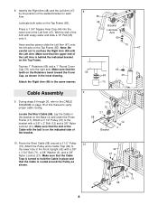
...this manual to hold the Cable in the bracket on the Top Frame. 70 47 Tap two 1" Retainers (69) and a 1" Round Cover Cap (70) onto the right axle. Attach a 3 1/2" Pulley (15) to the lower hole in the same manner. 70 Cable Assembly 9. Make sure that the Cable is routed around a 3 ...1/2" Pulley 10 (15). Note: Be careful not to the CABLE DIAGRAM on the Top Frame (55). Wet the end of the Cable with soapy water and slide a 10" Pad (45) onto it....
...this manual to hold the Cable in the bracket on the Top Frame. 70 47 Tap two 1" Retainers (69) and a 1" Round Cover Cap (70) onto the right axle. Attach a 3 1/2" Pulley (15) to the lower hole in the same manner. 70 Cable Assembly 9. Make sure that the Cable is routed around a 3 ...1/2" Pulley 10 (15). Note: Be careful not to the CABLE DIAGRAM on the Top Frame (55). Wet the end of the Cable with soapy water and slide a 10" Pad (45) onto it....
English Manual
Page 11
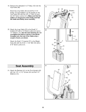
Attach the Long Cable (23) to the Front Upright (42) with the 5/16" x 1 3/4" Bolt (72) and a 3 67 5/16" Nylon Locknut (3). 72 10 63 2 23 2 67 Seat Assembly 21 21. Do not overtighten the Nylon Locknut; it to the Weight Tube (63) with two 1/4" x 2 1/2" Screws (43) and two 1/4" Washers (10). 41 43 ...10 42 43 10 11 Make sure that the Cable is in the groove of turns, as shown. 23...
Attach the Long Cable (23) to the Front Upright (42) with the 5/16" x 1 3/4" Bolt (72) and a 3 67 5/16" Nylon Locknut (3). 72 10 63 2 23 2 67 Seat Assembly 21 21. Do not overtighten the Nylon Locknut; it to the Weight Tube (63) with two 1/4" x 2 1/2" Screws (43) and two 1/4" Washers (10). 41 43 ...10 42 43 10 11 Make sure that the Cable is in the groove of turns, as shown. 23...
English Manual
Page 18
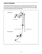
... been correctly routed, the weight system will not function properly and damage may occur. If the Cables have been assembled correctly. The numbers show the correct route for each Cable are labeled. Long Cable (23) 4 5 7 2 3 1-High Pulley 6 5-Long "U"-Bracket Short Cable (58) 4 3 2 1-Low Pulley Weight Stack-8 18 Use the diagram to make sure that the...
... been correctly routed, the weight system will not function properly and damage may occur. If the Cables have been assembled correctly. The numbers show the correct route for each Cable are labeled. Long Cable (23) 4 5 7 2 3 1-High Pulley 6 5-Long "U"-Bracket Short Cable (58) 4 3 2 1-Low Pulley Weight Stack-8 18 Use the diagram to make sure that the...


