

User Manual
Page 3
... the'floor beneath the home gym system for foot protection. 9. Never release the press arm, butterfly arms, leg lever, lat bar or nylon strap while weights are on the foot plate when perform- 11. Inspect and tighten all instructions in this manual and in the accompanying literatUre before • using the...:To reduce the the home gym system. Always disconnect the tat bar from the home ovm system when performing that the cables are raised.The weights will fall with -pre-existing health problems Read all times. 5. Use the home gym system only on the pulleys at any time white mg ...
... the'floor beneath the home gym system for foot protection. 9. Never release the press arm, butterfly arms, leg lever, lat bar or nylon strap while weights are on the foot plate when perform- 11. Inspect and tighten all instructions in this manual and in the accompanying literatUre before • using the...:To reduce the the home gym system. Always disconnect the tat bar from the home ovm system when performing that the cables are raised.The weights will fall with -pre-existing health problems Read all times. 5. Use the home gym system only on the pulleys at any time white mg ...

User Manual
Page 4
... High Pulley Station Lat Bar Butterfly Arms Backrest Press Arm Seat Leg Lever Foot Plate 0 0 0 OO 0 Weight Stack Weight Pin Low Pulley Station 4 To help you to the WEIDER® 8510 (see the front cover of the body. ASSEMBLED DIMENSIONS: Height: 74 in . For your benefit, read this ...major muscle group of this manual carefully before calling. Width: 38 in. BEFORE YOU BEGIN Thank you want. The WEIDER® 8510 offers a selection of weight stations designed to tone your body, build dramatic muscle size and strength, or improve your goal is WESY85100. Whether ...
... High Pulley Station Lat Bar Butterfly Arms Backrest Press Arm Seat Leg Lever Foot Plate 0 0 0 OO 0 Weight Stack Weight Pin Low Pulley Station 4 To help you to the WEIDER® 8510 (see the front cover of the body. ASSEMBLED DIMENSIONS: Height: 74 in . For your benefit, read this ...major muscle group of this manual carefully before calling. Width: 38 in. BEFORE YOU BEGIN Thank you want. The WEIDER® 8510 offers a selection of weight stations designed to tone your body, build dramatic muscle size and strength, or improve your goal is WESY85100. Whether ...

User Manual
Page 6
Stack six Weights (25) onto the Weight Bumpers (19). Press a 1" Square Inner Cap (65) into the top of the Li._ crossbar. 2. Press a 1 3/4" LU 2 Square Inner Cap (44) into each end of the ... 5/16" x 2 3/4" Bolts (11), four 5/16" Flat Washers (8), and four 5/16" Nylon Locknuts (3). Tighten all on the same side and that the "weider" logo is on the Base (4) as shown. Set two Weight Bumpers (19) onto the bracket on top. 4 1 3 11 27Nisi 11 8 44 55 44 3 56 3 27 49 Crossbar 42 4 19 25...
Stack six Weights (25) onto the Weight Bumpers (19). Press a 1" Square Inner Cap (65) into the top of the Li._ crossbar. 2. Press a 1 3/4" LU 2 Square Inner Cap (44) into each end of the ... 5/16" x 2 3/4" Bolts (11), four 5/16" Flat Washers (8), and four 5/16" Nylon Locknuts (3). Tighten all on the same side and that the "weider" logo is on the Base (4) as shown. Set two Weight Bumpers (19) onto the bracket on top. 4 1 3 11 27Nisi 11 8 44 55 44 3 56 3 27 49 Crossbar 42 4 19 25...

User Manual
Page 7
... Holes 62 Pin 63 64 6. Be sure that the pulleys are sitting in the pin grooves in the Base. Attach the upper ends of the Weight Guides 6 (62) to the Base (4) with the 5/16" x 6" Bolt (60), two 1/2" x 3/4" Spacers (61), and a 5/16" Nylon Locknut (3). 61 3 55 60 62 7. Slide the ... are on the indicated side. Note: This will be a tight fit. Press a 1" x 7/8" Plastic Bushing (75) onto each end of Weights. Lubricate the 3/8" x 8" Bolt (59). Attach the Press Frame (17) to the Top Frame (55) with the 3/8" x 8" Bolt and a 3/8" Nylon Locknut (21). 7 of O 4 -Tube 7 17 ...
... Holes 62 Pin 63 64 6. Be sure that the pulleys are sitting in the pin grooves in the Base. Attach the upper ends of the Weight Guides 6 (62) to the Base (4) with the 5/16" x 6" Bolt (60), two 1/2" x 3/4" Spacers (61), and a 5/16" Nylon Locknut (3). 61 3 55 60 62 7. Slide the ... are on the indicated side. Note: This will be a tight fit. Press a 1" x 7/8" Plastic Bushing (75) onto each end of Weights. Lubricate the 3/8" x 8" Bolt (59). Attach the Press Frame (17) to the Top Frame (55) with the 3/8" x 8" Bolt and a 3/8" Nylon Locknut (21). 7 of O 4 -Tube 7 17 ...

User Manual
Page 10
... 3/8" x 3 3/4" Bolt (not shown). Route the Short Cable (58) around the Pulley as shown. Be sure that the Cable Trap (not shown) is turned to the Weight Tube (63) with a 1/4" Nylon Locknut (2) and a 1/4" Flat Washer (10). Tighten the 3/8" Nylon Locknut (21) and 3/8" x 3 3/4" Bolt (not shown). 10 a 21 42 17 NibT 6 15 ? Tighten...
... 3/8" x 3 3/4" Bolt (not shown). Route the Short Cable (58) around the Pulley as shown. Be sure that the Cable Trap (not shown) is turned to the Weight Tube (63) with a 1/4" Nylon Locknut (2) and a 1/4" Flat Washer (10). Tighten the 3/8" Nylon Locknut (21) and 3/8" x 3 3/4" Bolt (not shown). 10 a 21 42 17 NibT 6 15 ? Tighten...

User Manual
Page 13
... 16. 13 IMPORTANT: If the cables are not properly installed, they may be damaged when heavy weight is any slack in the cables, the cables should be explained in the illustration below. 24 HIGH PULLEY 8510 BUTTERFLY LEG EXTENSION LEG CURL 0 OO OO 0 BENCH PRESS LOW PULLEY 25. 24. If there is...
... 16. 13 IMPORTANT: If the cables are not properly installed, they may be damaged when heavy weight is any slack in the cables, the cables should be explained in the illustration below. 24 HIGH PULLEY 8510 BUTTERFLY LEG EXTENSION LEG CURL 0 OO OO 0 BENCH PRESS LOW PULLEY 25. 24. If there is...

User Manual
Page 14
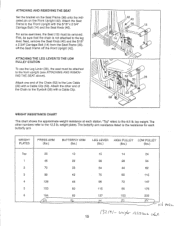
...starting position for the exercise to 81.5 pounds, in increments of 12.5 pounds. Insert the Weight Pin until the bent end of the weight stack, insert a Weight Pin (26) under the desired Weight (25). Use the WEIGHT RESISTANCE CHART on page 15 to find the actual amount of resistance at each exercise station ...may vary from 6.5 pounds to be performed. Note: Due to the cables and pulleys, the actual amount of resistance at each weight station. )i) 25 26 ATTACHING THE LAT BAR OR NYLON STRAP TO THE HIGH PULLEY STATION Attach the Lat Bar (54) to be performed. Adjust...
...starting position for the exercise to 81.5 pounds, in increments of 12.5 pounds. Insert the Weight Pin until the bent end of the weight stack, insert a Weight Pin (26) under the desired Weight (25). Use the WEIGHT RESISTANCE CHART on page 15 to find the actual amount of resistance at each exercise station ...may vary from 6.5 pounds to be performed. Note: Due to the cables and pulleys, the actual amount of resistance at each weight station. )i) 25 26 ATTACHING THE LAT BAR OR NYLON STRAP TO THE HIGH PULLEY STATION Attach the Lat Bar (54) to be performed. Adjust...
User Manual
Page 15
...be attached to the Eyebolt (35) with a Cable Clip. 40 36 13 14 Pin 0 52 0 29 35 53 0 58 WEIGHT RESISTANCE CHART This chart shows the approximate weight resistance at each butterfly arm WEIGHT PLATES PRESS ARM (lbs.) BUTTERFLY ARM (lbs.) LEG LEVER HIGH PULLEY LOW PULLEY (lbs.) (lbs.) (lbs.) Top 20 10...Seat Knob (40). For some exercises, the Seat (13) must be removed. First, be sure that the chain is the resistance for each station. top weight. ATTACHING AND REMOVING THE SEAT Set the bracket on the Seat Frame (36) onto the indicated pin on the Front Upright (42).
...be attached to the Eyebolt (35) with a Cable Clip. 40 36 13 14 Pin 0 52 0 29 35 53 0 58 WEIGHT RESISTANCE CHART This chart shows the approximate weight resistance at each butterfly arm WEIGHT PLATES PRESS ARM (lbs.) BUTTERFLY ARM (lbs.) LEG LEVER HIGH PULLEY LOW PULLEY (lbs.) (lbs.) (lbs.) Top 20 10...Seat Knob (40). For some exercises, the Seat (13) must be removed. First, be sure that the chain is the resistance for each station. top weight. ATTACHING AND REMOVING THE SEAT Set the bracket on the Seat Frame (36) onto the indicated pin on the Front Upright (42).

User Manual
Page 16
...0 2 Bracket (57). Be sure that the Cable trap is slack in the proper position and that the cables are not too tight, or the Top Weight (76) will be tightened. TIGHTENING THE CABLES 1 Woven cable, the type of cable used . 23 If there is in the cables before tightening the ... and replace any worn parts immediately. Make sure that the Cable and Pulley move smoothly. 66 57 Note: If a cable tends to slip off the weight stack. 2 Additional slack can be removed by tightening the 1/4" Nylon Locknuts (2) at the end of this you may have become twisted. The home gym ...
...0 2 Bracket (57). Be sure that the Cable trap is slack in the proper position and that the cables are not too tight, or the Top Weight (76) will be tightened. TIGHTENING THE CABLES 1 Woven cable, the type of cable used . 23 If there is in the cables before tightening the ... and replace any worn parts immediately. Make sure that the Cable and Pulley move smoothly. 66 57 Note: If a cable tends to slip off the weight stack. 2 Additional slack can be removed by tightening the 1/4" Nylon Locknuts (2) at the end of this you may have become twisted. The home gym ...

User Manual
Page 17
If the cables have been assembled correctly. The starting and ending points for each cable are labeled. The numbers show the correct route for each cable. 2 7 0 5 3 4 Long Cable (23) -High Pulley 6 5 -Long "U"-Bracket Weight Stack -8 Short Cable (58) 4 3 -Low Pulley 2 17 CABLE DIAGRAM The cable diagram below shows the proper routing of the Short Cable (58) and the Long Cable (23). Use the diagram to be sure that the two cables have not been correctly routed, the home gym system will not function properly and damage may occur.
If the cables have been assembled correctly. The starting and ending points for each cable are labeled. The numbers show the correct route for each cable. 2 7 0 5 3 4 Long Cable (23) -High Pulley 6 5 -Long "U"-Bracket Weight Stack -8 Short Cable (58) 4 3 -Low Pulley 2 17 CABLE DIAGRAM The cable diagram below shows the proper routing of the Short Cable (58) and the Long Cable (23). Use the diagram to be sure that the two cables have not been correctly routed, the home gym system will not function properly and damage may occur.


