

English Manual
Page 2
WEIDER is a registered trademark of this manual. Remove the PART IDENTIFICATION CHART and PART LIST/EXPLODED DRAWING before beginning assembly. TABLE OF CONTENTS WARNING DECAL PLACEMENT 3 IMPORTANT PRECAUTIONS 4 BEFORE YOU BEGIN 5 ASSEMBLY 6 ADJUSTMENTS 20 WEIGHT RESISTANCE CHART 22 CABLE DIAGRAMS 23 TROUBLESHOOTING 24 EXERCISE GUIDELINES 25 ORDERING REPLACEMENT PARTS Back Cover LIMITED WARRANTY Back Cover Note: A PART IDENTIFICATION CHART and a PART LIST/EXPLODED DRAWING are attached in the center of ICON Health & Fitness, Inc. 2
WEIDER is a registered trademark of this manual. Remove the PART IDENTIFICATION CHART and PART LIST/EXPLODED DRAWING before beginning assembly. TABLE OF CONTENTS WARNING DECAL PLACEMENT 3 IMPORTANT PRECAUTIONS 4 BEFORE YOU BEGIN 5 ASSEMBLY 6 ADJUSTMENTS 20 WEIGHT RESISTANCE CHART 22 CABLE DIAGRAMS 23 TROUBLESHOOTING 24 EXERCISE GUIDELINES 25 ORDERING REPLACEMENT PARTS Back Cover LIMITED WARRANTY Back Cover Note: A PART IDENTIFICATION CHART and a PART LIST/EXPLODED DRAWING are attached in the center of ICON Health & Fitness, Inc. 2
English Manual
Page 4
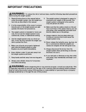
... risk of serious injury, read the following important precautions before using . If you are on the foot plate when performing an exercise that the cables remain on a level surface. Replace any commercial, rental, or institutional setting. 4. WARNING: Before beginning this manual. 2. Read all times. ...parts are raised; Do not use it. 14. Make sure that could cause the weight system to protect the floor. 5. If the cables bind as described in any worn parts immediately. 6. Never release the butterfly arms, leg lever, lat bar, or accessories while the weights...
... risk of serious injury, read the following important precautions before using . If you are on the foot plate when performing an exercise that the cables remain on a level surface. Replace any commercial, rental, or institutional setting. 4. WARNING: Before beginning this manual. 2. Read all times. ...parts are raised; Do not use it. 14. Make sure that could cause the weight system to protect the floor. 5. If the cables bind as described in any worn parts immediately. 6. Never release the butterfly arms, leg lever, lat bar, or accessories while the weights...

English Manual
Page 6
... as you will assemble the arms and the leg lever. Seat Assembly-During the final stage you assemble it will attach the cables and pulleys that there is completed. Cable Assembly-During this stage you identify the small parts used . By setting aside plenty of this page. The parts needed for the...
... as you will assemble the arms and the leg lever. Seat Assembly-During the final stage you assemble it will attach the cables and pulleys that there is completed. Cable Assembly-During this stage you identify the small parts used . By setting aside plenty of this page. The parts needed for the...

English Manual
Page 9
... M10 Nylon Locknuts (80). Do not tighten the Locknuts yet. Press a 25mm x 70mm Inner Cap (31) into the Foot Plate (4). Attach a 90mm Pulley (46) and a Cable Trap (48) to the Squat Frame (9) with two M10 x 70mm Bolts (70) and two M10 Nylon Locknuts (80). 5. Attach the Foot Plate to align the... 9 53 80 83 46 48 61 53 Do not tighten the Locknuts yet. 5 1 80 30 6. Attach the Seat Frame (8) to be loose until the High Cable (not shown) is assembled around the Pulley. Press two 50mm Square Inner Caps (30) into the 7 bottom of the Squat Frame (9). Attach the other three...
... M10 Nylon Locknuts (80). Do not tighten the Locknuts yet. Press a 25mm x 70mm Inner Cap (31) into the Foot Plate (4). Attach a 90mm Pulley (46) and a Cable Trap (48) to the Squat Frame (9) with two M10 x 70mm Bolts (70) and two M10 Nylon Locknuts (80). 5. Attach the Foot Plate to align the... 9 53 80 83 46 48 61 53 Do not tighten the Locknuts yet. 5 1 80 30 6. Attach the Seat Frame (8) to be loose until the High Cable (not shown) is assembled around the Pulley. Press two 50mm Square Inner Caps (30) into the 7 bottom of the Squat Frame (9). Attach the other three...

English Manual
Page 13
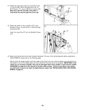
...x 52mm Bolt (68) and an M10 Nylon Locknut (80). Attach the eyelet on page 23 as you assemble the cables and to the Short Swivel Bracket (50) with an M10 x 45mm Bolt (61) and an M10 Nylon Locknut (80... 20mm Shoulder Bolt (76) and an M8 17 Nylon Locknut (83). 17. Wrap the Low Cable (55) over a 90mm Pulley (46). Make sure the Cable Trap is oriented to the Right Butterfly Arm (13) with an M10 x 60mm Bolt (72...55 83 80 55 80 48 46 49 80 61 13 68 85 47 55 80 72 5 19. Make sure the Cable Trap is turned to the Front Upright (5) with an M10 x 52mm Bolt (68) and an M10 Nylon Locknut (...
...x 52mm Bolt (68) and an M10 Nylon Locknut (80). Attach the eyelet on page 23 as you assemble the cables and to the Short Swivel Bracket (50) with an M10 x 45mm Bolt (61) and an M10 Nylon Locknut (80... 20mm Shoulder Bolt (76) and an M8 17 Nylon Locknut (83). 17. Wrap the Low Cable (55) over a 90mm Pulley (46). Make sure the Cable Trap is oriented to the Right Butterfly Arm (13) with an M10 x 60mm Bolt (72...55 83 80 55 80 48 46 49 80 61 13 68 85 47 55 80 72 5 19. Make sure the Cable Trap is turned to the Front Upright (5) with an M10 x 52mm Bolt (68) and an M10 Nylon Locknut (...

English Manual
Page 14
... (48) to the bracket on the Base (1) with an M10 x 45mm Bolt (61) and an M10 Nylon Locknut (80). Make sure the Cable Trap (48) is shown from the other side 20 of the bracket on the Base (1) with an M10 x 45mm Bolt (61) and an M10 Nylon ...). Tighten the M10 Nylon Locknut (not shown) securing the Pulley to the bracket on the Squat Frame (9). Wrap the Low Cable (55) under a 90mm Pulley 21 (46). Attach the Pulley and a Long Cable Trap (85) to the Squat Frame. 46 48 61 55 1 80 48 9 46 55 24. Attach the Pulley and...
... (48) to the bracket on the Base (1) with an M10 x 45mm Bolt (61) and an M10 Nylon Locknut (80). Make sure the Cable Trap (48) is shown from the other side 20 of the bracket on the Base (1) with an M10 x 45mm Bolt (61) and an M10 Nylon ...). Tighten the M10 Nylon Locknut (not shown) securing the Pulley to the bracket on the Squat Frame (9). Wrap the Low Cable (55) under a 90mm Pulley 21 (46). Attach the Pulley and a Long Cable Trap (85) to the Squat Frame. 46 48 61 55 1 80 48 9 46 55 24. Attach the Pulley and...

English Manual
Page 15
.... Attach the Pulley to the Top Frame (11) with an M10 x 45mm Bolt (61) and an M10 Nylon Locknut (80). 28. Wrap the Low Cable (55) over a 90mm Pulley 27 (46). Wrap the Low Cable (55) over a 90mm Pulley 28 (46). Thread an M12 Nut (87) all the way onto the Low... Nylon Locknut (80). Attach the Pulley to the indicated end of the Pulley. 26. Wrap the Low Cable (55) under a 90mm Pulley 26 (46). Screw the Cable partway into the Weight Tube (23). Wrap the Low Cable (55) over a 90mm Pulley 25 (46). Set a 50mm Washer (88) on the Weight Tube 29 (23...
.... Attach the Pulley to the Top Frame (11) with an M10 x 45mm Bolt (61) and an M10 Nylon Locknut (80). 28. Wrap the Low Cable (55) over a 90mm Pulley 27 (46). Wrap the Low Cable (55) over a 90mm Pulley 28 (46). Thread an M12 Nut (87) all the way onto the Low... Nylon Locknut (80). Attach the Pulley to the indicated end of the Pulley. 26. Wrap the Low Cable (55) under a 90mm Pulley 26 (46). Screw the Cable partway into the Weight Tube (23). Wrap the Low Cable (55) over a 90mm Pulley 25 (46). Set a 50mm Washer (88) on the Weight Tube 29 (23...

English Manual
Page 16
...80 59 77 65 77 Large Ball 46 54 77 11 80 59 59 65 77 32. Attach the Pulley and a Cable Trap (48) to the Base (1) with an M10 x 48mm Bolt (86) and an M10 Nylon Locknut (80). ...59), two M10 Washers (77), and an M10 Nylon Locknut (80). 31. Make sure the Cable Trap is turned to hold the Cable in the groove of the Pulley. 54 80 86 48 77 46 1 33. Attach the Pulley and...of holes from the bottom of the Pulley. 16 39 86 80 48 46 54 Make sure the Cable Trap is turned to hold the Cable in the groove of the "U"-bracket (39) with an M10 x 48mm Bolt (86), an M10 ...
...80 59 77 65 77 Large Ball 46 54 77 11 80 59 59 65 77 32. Attach the Pulley and a Cable Trap (48) to the Base (1) with an M10 x 48mm Bolt (86) and an M10 Nylon Locknut (80). ...59), two M10 Washers (77), and an M10 Nylon Locknut (80). 31. Make sure the Cable Trap is turned to hold the Cable in the groove of the Pulley. 54 80 86 48 77 46 1 33. Attach the Pulley and...of holes from the bottom of the Pulley. 16 39 86 80 48 46 54 Make sure the Cable Trap is turned to hold the Cable in the groove of the "U"-bracket (39) with an M10 x 48mm Bolt (86), an M10 ...

English Manual
Page 17
...an M6 x 65mm Screw (81), and an M6 Washer (74). 20 8 74 81 67 17 Attach the Pulley and a Cable Trap (48) to the Seat Frame (8) with an M10 x 48mm Bolt (86), an M10 Washer (77), and an M10... Nylon Locknut (80). Attach a 90mm Pulley (46) inside the Front Leg (7), over the High Cable (54), with an M10 x 67mm Bolt (65), two 12.5mm Spacers (59), two M10 Washers (77), and an ...M10 Nylon Locknut (80). 36. Make sure the Cable Trap is turned to hold the Cable in the groove of the Pulley. 35. Attach a 90mm Pulley (46) inside the Leg Lever ...
...an M6 x 65mm Screw (81), and an M6 Washer (74). 20 8 74 81 67 17 Attach the Pulley and a Cable Trap (48) to the Seat Frame (8) with an M10 x 48mm Bolt (86), an M10 Washer (77), and an M10... Nylon Locknut (80). Attach a 90mm Pulley (46) inside the Front Leg (7), over the High Cable (54), with an M10 x 67mm Bolt (65), two 12.5mm Spacers (59), two M10 Washers (77), and an ...M10 Nylon Locknut (80). 36. Make sure the Cable Trap is turned to hold the Cable in the groove of the Pulley. 35. Attach a 90mm Pulley (46) inside the Leg Lever ...
English Manual
Page 19
... there is any slack in ADJUSTMENTS, beginning on page 23 of the remaining parts will be explained in the cables, you will need to be damaged when heavy weight is inserted all parts have been properly tightened. 41. Attach the tether on page 24. 19 ... Bolt is used. Make sure that all the way through the Front Leg. 42. Make sure that the shoulder of the cables does not move smoothly over the pulleys. See the CABLE DIAGRAMS on the following page. See TROUBLESHOOTING AND MAINTENANCE on the Long Pins (57) to the Front Leg 41 (7) with...
... there is any slack in ADJUSTMENTS, beginning on page 23 of the remaining parts will be explained in the cables, you will need to be damaged when heavy weight is inserted all parts have been properly tightened. 41. Attach the tether on page 24. 19 ... Bolt is used. Make sure that all the way through the Front Leg. 42. Make sure that the shoulder of the cables does not move smoothly over the pulleys. See the CABLE DIAGRAMS on the following page. See TROUBLESHOOTING AND MAINTENANCE on the Long Pins (57) to the Front Leg 41 (7) with...

English Manual
Page 21
... chart below shows the approximate weight resistance at each station may vary due to differences in individual weight plates as well as friction between the cables, pulleys, and weight guides. top weight. The other numbers refer to the 6 lb. WEIGHT Top 1 2 3 4 5 6 LEG PRESS (lbs.) 15 36 55 76 97 118 145...
... chart below shows the approximate weight resistance at each station may vary due to differences in individual weight plates as well as friction between the cables, pulleys, and weight guides. top weight. The other numbers refer to the 6 lb. WEIGHT Top 1 2 3 4 5 6 LEG PRESS (lbs.) 15 36 55 76 97 118 145...

English Manual
Page 22
... 8 4 14 7 9 6 5 3 6 7 23 The numbers show the approximate lengths and the proper routing of the High Cable (54) and the Low Cable (55). CABLE DIAGRAMS The cable diagrams show the correct route for each cable. Make sure that the cables and the cable traps have not been correctly routed, the weight system will not function properly and damage...
... 8 4 14 7 9 6 5 3 6 7 23 The numbers show the approximate lengths and the proper routing of the High Cable (54) and the Low Cable (55). CABLE DIAGRAMS The cable diagrams show the correct route for each cable. Make sure that the cables and the cable traps have not been correctly routed, the weight system will not function properly and damage...
English Manual
Page 23
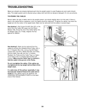
...lifted off the pulleys repeatedly, it . Do not use solvents. First loosen the M12 Nut (87) on the end of the Pulley. If the cables need to be replaced, see ORDERING REPLACEMENT PARTS on the weight system, can be cleaned using a damp cloth and mild non-abrasive detergent. Slack can...the Weight Tube (23). Finally, retighten the Nut against the Washer. 55 88 87 23 See drawing 2. Remove the cable and reinstall it may have become twisted. TIGHTENING THE CABLES Woven cable, the type of the weight stack. If there is slack in the "U"-bracket with the Bolt and Locknut. Screw ...
...lifted off the pulleys repeatedly, it . Do not use solvents. First loosen the M12 Nut (87) on the end of the Pulley. If the cables need to be replaced, see ORDERING REPLACEMENT PARTS on the weight system, can be cleaned using a damp cloth and mild non-abrasive detergent. Slack can...the Weight Tube (23). Finally, retighten the Nut against the Washer. 55 88 87 23 See drawing 2. Remove the cable and reinstall it may have become twisted. TIGHTENING THE CABLES Woven cable, the type of the weight stack. If there is slack in the "U"-bracket with the Bolt and Locknut. Screw ...

English Manual
Page 27
... parts immediately. CHANGING THE WEIGHT SETTING To change the setting of the Chain between the Lat Bar and the Cable with a damp cloth and a mild, non-abrasive detergent. Note: Due to the cables and pulleys, the amount of resistance at each weight station. 62 22 21 ATTACHING THE ACCESSORIES TO A PULLEY... guide to adjust the weight system. The Lat Bar (26) or the Handle (not shown) can be attached between the Lat Bar and the Cable so that the bent end touches the weight stack. ADJUSTMENTS This section explains how to see the correct form for each time the weight system...
... parts immediately. CHANGING THE WEIGHT SETTING To change the setting of the Chain between the Lat Bar and the Cable with a damp cloth and a mild, non-abrasive detergent. Note: Due to the cables and pulleys, the amount of resistance at each weight station. 62 22 21 ATTACHING THE ACCESSORIES TO A PULLEY... guide to adjust the weight system. The Lat Bar (26) or the Handle (not shown) can be attached between the Lat Bar and the Cable so that the bent end touches the weight stack. ADJUSTMENTS This section explains how to see the correct form for each time the weight system...
English Manual
Page 31
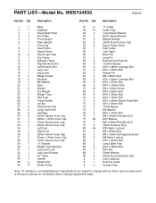
...2 Long Swivel Bracket 50 1 Short Swivel Bracket 51 2 Weight Bumper 52 2 25mm Round Cover Cap 53 4 Squat Frame Roller 54 1 High Cable 55 1 Low Cable 56 1 Short Pin 57 2 Long Pin 58 2 Butterfly Arm Bushing 59 8 12.5mm Spacer 60 2 M10 x 68mm Carriage Bolt 61 9 ...49 M10 Nylon Locknut 81 1 M6 x 65mm Bolt 82 3 M4 x 16mm Self-tapping Screw 83 6 M8 Nylon Locknut 84 1 M10 x 92mm Bolt 85 2 Long Cable Trap 86 4 M10 x 48mm Bolt 87 1 M12 Nut 88 1 50mm Washer 89 2 50mm Round Butterfly Cap # 1 User's Manual # 1 Exercise Guide # 2 Grease...
...2 Long Swivel Bracket 50 1 Short Swivel Bracket 51 2 Weight Bumper 52 2 25mm Round Cover Cap 53 4 Squat Frame Roller 54 1 High Cable 55 1 Low Cable 56 1 Short Pin 57 2 Long Pin 58 2 Butterfly Arm Bushing 59 8 12.5mm Spacer 60 2 M10 x 68mm Carriage Bolt 61 9 ...49 M10 Nylon Locknut 81 1 M6 x 65mm Bolt 82 3 M4 x 16mm Self-tapping Screw 83 6 M8 Nylon Locknut 84 1 M10 x 92mm Bolt 85 2 Long Cable Trap 86 4 M10 x 48mm Bolt 87 1 M12 Nut 88 1 50mm Washer 89 2 50mm Round Butterfly Cap # 1 User's Manual # 1 Exercise Guide # 2 Grease...


