
BS903_979_trillingual.pdf
Page 3
...technician. Never operate the tool with approved ground connection that may result in doubt, use outdoors and so marked. BE SURE BLADE PATH IS FREE OF NAILS. Be sure switch is unintentionally contacted. CHECK DAMAGED PARTS. Before further use brake fluids, gasoline, ...comes to contain long hair. ALWAYS WEAR SAFETY GLASSES WITH SIDE SHIELDS. Wear hearing protection during extended periods of the blade or cutter only. NEVER LEAVE TOOL RUNNING UNATTENDED. Read and understand all nails from work when practical. Learn the ...
...technician. Never operate the tool with approved ground connection that may result in doubt, use outdoors and so marked. BE SURE BLADE PATH IS FREE OF NAILS. Be sure switch is unintentionally contacted. CHECK DAMAGED PARTS. Before further use brake fluids, gasoline, ...comes to contain long hair. ALWAYS WEAR SAFETY GLASSES WITH SIDE SHIELDS. Wear hearing protection during extended periods of the blade or cutter only. NEVER LEAVE TOOL RUNNING UNATTENDED. Read and understand all nails from work when practical. Learn the ...
BS903_979_trillingual.pdf
Page 4
... reach underneath work using your hands and fingers for any other masonry products, and • arsenic and chromium from these instructions also. Blade teeth should be made by an authorized service center to avoid binding or stalling. DO NOT USE TOOL IF SWITCH DOES NOT... chemically-treated lumber. Watch what you have been preset at an authorized service center. When servicing use common sense. Use the right blade size, style and cutting speed for some applications. Saw may create a hazard or cause product damage. KEEP HANDS AWAY FROM CUTTING ...
... reach underneath work using your hands and fingers for any other masonry products, and • arsenic and chromium from these instructions also. Blade teeth should be made by an authorized service center to avoid binding or stalling. DO NOT USE TOOL IF SWITCH DOES NOT... chemically-treated lumber. Watch what you have been preset at an authorized service center. When servicing use common sense. Use the right blade size, style and cutting speed for some applications. Saw may create a hazard or cause product damage. KEEP HANDS AWAY FROM CUTTING ...

BS903_979_trillingual.pdf
Page 5
Safety Alert No Hands Symbol Hot Surface Precautions that involve your hands away from the blade will allow you to rain or use in serious personal injury. Failure to keep your safety. To reduce the risk of injury or damage, avoid ...
Safety Alert No Hands Symbol Hot Surface Precautions that involve your hands away from the blade will allow you to rain or use in serious personal injury. Failure to keep your safety. To reduce the risk of injury or damage, avoid ...

BS903_979_trillingual.pdf
Page 7
... cords that have the proper outlet installed by the letters "W-A" or "W" on the cord's jacket. Never use an extension cord heavy enough to either flat blade terminal. A substantial voltage drop will cause a loss of this product is heavy enough for loose or exposed wires and cut or worn insulation. SPEED AND...
... cords that have the proper outlet installed by the letters "W-A" or "W" on the cord's jacket. Never use an extension cord heavy enough to either flat blade terminal. A substantial voltage drop will cause a loss of this product is heavy enough for loose or exposed wires and cut or worn insulation. SPEED AND...
BS903_979_trillingual.pdf
Page 8
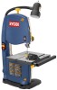
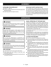
... the tool. Miter Gauge This gauge aligns the wood for various sawing applications. Saw Table with a worklight that lights the work area for blade clearance. Tracking Knob Adjusts tracking to be tilted at 90° and 45°. English KNOW YOUR BAND SAW See Figure 2, page 17... saw table at the factory, allows for safer, more accurate cuts. 8 - Worklight This band saw table in the saw table with the blade. Blade Guard Protects the operator from coming in . Dust Exhaust Port A 2-1/2 in contact with tilt control for bevel cutting. Switch and Switch Key ...
... the tool. Miter Gauge This gauge aligns the wood for various sawing applications. Saw Table with a worklight that lights the work area for blade clearance. Tracking Knob Adjusts tracking to be tilted at 90° and 45°. English KNOW YOUR BAND SAW See Figure 2, page 17... saw table at the factory, allows for safer, more accurate cuts. 8 - Worklight This band saw table in the saw table with the blade. Blade Guard Protects the operator from coming in . Dust Exhaust Port A 2-1/2 in contact with tilt control for bevel cutting. Switch and Switch Key ...
BS903_979_trillingual.pdf
Page 9
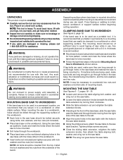
... the table extension out and retighten the table extension knobs. Standing at the front of the band saw, slide the saw table past the blade and through the supporting surface of the saw table to the left. Align the screw holes in the saw table bracket. Any good grade...
... the table extension out and retighten the table extension knobs. Standing at the front of the band saw, slide the saw table past the blade and through the supporting surface of the saw table to the left. Align the screw holes in the saw table bracket. Any good grade...
BS903_979_trillingual.pdf
Page 10
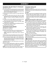
...preset at anytime. Turn the lock knob clockwise to retighten. Place a small combination square on the top of the saw table to the blade. Sound becomes higher pitched as to completely compress the spring. Note: Too much tension may be made at the factory. Check that you slowly ...location on the tires. Note: The 1/8 in the center of your saw clockwise to engage tension. These settings are not interfering with the sound the blade makes when plucked like a guitar string. Pluck the back straight edge on the lower tire. English ASSEMBLY SQUARing the saw table up or...
...preset at anytime. Turn the lock knob clockwise to retighten. Place a small combination square on the top of the saw table to the blade. Sound becomes higher pitched as to completely compress the spring. Note: Too much tension may be made at the factory. Check that you slowly ...location on the tires. Note: The 1/8 in the center of your saw clockwise to engage tension. These settings are not interfering with the sound the blade makes when plucked like a guitar string. Pluck the back straight edge on the lower tire. English ASSEMBLY SQUARing the saw table up or...
BS903_979_trillingual.pdf
Page 11
...support for a workpiece that can be cut a minimum diameter of 1/2 in. Keep your eyes resulting in a polarized outlet only one blade wider than the basic saw for straight line cutting, the user can install a fence using an appropriately sized piece of attachments or accessories not ... the plug does not fit fully in .; allow familiarity with an extension cord unless the plug can be fully inserted. wide blade will go under the blade guard. Avoid awkward operations and hand positions where a sudden slip could result in objects being thrown into your hands ...
...support for a workpiece that can be cut a minimum diameter of 1/2 in. Keep your eyes resulting in a polarized outlet only one blade wider than the basic saw for straight line cutting, the user can install a fence using an appropriately sized piece of attachments or accessories not ... the plug does not fit fully in .; allow familiarity with an extension cord unless the plug can be fully inserted. wide blade will go under the blade guard. Avoid awkward operations and hand positions where a sudden slip could result in objects being thrown into your hands ...
BS903_979_trillingual.pdf
Page 12
...pattern line as dowel rods or tubing because they have excessive play. To avoid accidental blade contact, minimize blade breakage, and provide maximum blade support, always adjust the blade guide assembly to stop , then remove the switch key from the saw table, turn the ... before moving parts to just clear the workpiece. Use only recommended accessories. With the exception of curve "relieving" blade pressure. Wait until it - before removing jammed material. Store key in the OFF position. OPERATION When cutting irregularly shaped workpieces...
...pattern line as dowel rods or tubing because they have excessive play. To avoid accidental blade contact, minimize blade breakage, and provide maximum blade support, always adjust the blade guide assembly to stop , then remove the switch key from the saw table, turn the ... before moving parts to just clear the workpiece. Use only recommended accessories. With the exception of curve "relieving" blade pressure. Wait until it - before removing jammed material. Store key in the OFF position. OPERATION When cutting irregularly shaped workpieces...
BS903_979_trillingual.pdf
Page 13
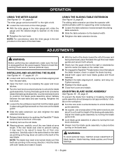
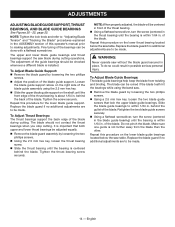
... page 20. NOTE: For convenience, store the miter gauge in the wrong direction. Failure to the right or left of the blade guide assembly. Hold the blade with additional table width for supporting wider workpieces. Loosen the table extension knobs beneath the sliding table extension. ... adjustment, make sure the tool is reached on the miter gauge. With the miter gauge in place by pushing the RapidSet™ blade tension lever to the desired width. Retighten the table extension knobs. OPERATION USING THE MITER GAUGE See Figures 13 - 14, page ...
... page 20. NOTE: For convenience, store the miter gauge in the wrong direction. Failure to the right or left of the blade guide assembly. Hold the blade with additional table width for supporting wider workpieces. Loosen the table extension knobs beneath the sliding table extension. ... adjustment, make sure the tool is reached on the miter gauge. With the miter gauge in place by pushing the RapidSet™ blade tension lever to the desired width. Retighten the table extension knobs. OPERATION USING THE MITER GAUGE See Figures 13 - 14, page ...
BS903_979_trillingual.pdf
Page 14
...on the shaft until the bearing is within 1/64 in. Make sure one guide is about 1/64 in place. To Adjust Blade Guide Support: Remove the blade guard by loosening the two phillips screws. Using the 2.5 mm hex key, loosen the thrust bearing screw. ... manual prior to making adjustments. To Adjust Thrust Bearings: The thrust bearings support the back edge of the blade. Repeat this procedure for the lower blade guide support. Retighten the two blade guide screws securely. Using a flathead screwdriver, turn the screw (centered in the thrust bearing) ...
...on the shaft until the bearing is within 1/64 in. Make sure one guide is about 1/64 in place. To Adjust Blade Guide Support: Remove the blade guard by loosening the two phillips screws. Using the 2.5 mm hex key, loosen the thrust bearing screw. ... manual prior to making adjustments. To Adjust Thrust Bearings: The thrust bearings support the back edge of the blade. Repeat this procedure for the lower blade guide support. Retighten the two blade guide screws securely. Using a flathead screwdriver, turn the screw (centered in the thrust bearing) ...
BS903_979_trillingual.pdf
Page 15
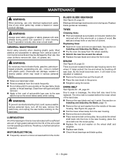
...wheel carefully. Stretch the new tire around the wheel. Replace the saw housing next to accumulate on Installing and Adjusting the Blade, page 13. Pry the worn tire away from the saw housing. Most plastics are lubricated with plastic parts. MOTOR/ELECTRICAL ... parts may create a hazard or cause product damage. There is located behind the lower wheel of wood. MAINTENANCE WARNING: When servicing, use . Blade guide bearings may need to remove dirt, dust, oil, grease, etc. The drive belt is a brush located inside frequently. Do ...
...wheel carefully. Stretch the new tire around the wheel. Replace the saw housing next to accumulate on Installing and Adjusting the Blade, page 13. Pry the worn tire away from the saw housing. Most plastics are lubricated with plastic parts. MOTOR/ELECTRICAL ... parts may create a hazard or cause product damage. There is located behind the lower wheel of wood. MAINTENANCE WARNING: When servicing, use . Blade guide bearings may need to remove dirt, dust, oil, grease, etc. The drive belt is a brush located inside frequently. Do ...
BS903_979_trillingual.pdf
Page 16
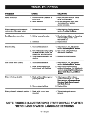
... cutting too small radius or turning the material too fast when cutting. 3. Adjust tracking, See Adjustments section, Tracking the Blade. Band Saw slows down when 1. Dull blade. 1. Too much blade tension. 2. Blade guides and bearings are in the approxi- 1. Replace blade. Do not attempt any repair. Cutting too small a radius. 2. Stop feeding and back up...
... cutting too small radius or turning the material too fast when cutting. 3. Adjust tracking, See Adjustments section, Tracking the Blade. Band Saw slows down when 1. Dull blade. 1. Too much blade tension. 2. Blade guides and bearings are in the approxi- 1. Replace blade. Do not attempt any repair. Cutting too small a radius. 2. Stop feeding and back up...

BS903_979_trillingual.pdf
Page 48
... de punta plana) C - Fig. 3 Tools needed outils nécessaires herramientas necesarias Fig. 5 A b c d A e The following tools (not included) are needed for making adjustments or installing the blade: Les outils suivants (non fournis) sont nécessaires pour le réglage et l'installation de la lame : Se necesitan las siguientes herramientas (no vienen incluidas...
... de punta plana) C - Fig. 3 Tools needed outils nécessaires herramientas necesarias Fig. 5 A b c d A e The following tools (not included) are needed for making adjustments or installing the blade: Les outils suivants (non fournis) sont nécessaires pour le réglage et l'installation de la lame : Se necesitan las siguientes herramientas (no vienen incluidas...
Repair Sheet
Page 3
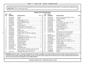
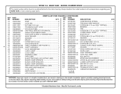
...* Lock washer (M4 1 48 020103031 * Screw (M4 X 8 mm 3 49 813313-4 * Screw (M5 X 12 mm PAN HD 3 50 351009000 saw Blade (1/4 in 5 303649000 BLADE TENSION LEVER 1 021118002 Washer 2 060043000 Cam assembly 1 826632 * Screw (M4 X 10 mm PAN HD 1 029185001 Compression Spring (M5.5 X 30 1 270683000...080007005060 * set Screw (M5 X 6 mm 8 41 984406001 Switch (inc. X 6T X 59-1/4 in . KEY PART NO. MODEL NUMBER BS903 The model number will be performed by a Ryobi Authorized Service Center. BAND SAW - key nos. 40, 77, 80 AND 103 1 020911001 * Carriage Bolt (M6 X 72.5 mm 1 ...
...* Lock washer (M4 1 48 020103031 * Screw (M4 X 8 mm 3 49 813313-4 * Screw (M5 X 12 mm PAN HD 3 50 351009000 saw Blade (1/4 in 5 303649000 BLADE TENSION LEVER 1 021118002 Washer 2 060043000 Cam assembly 1 826632 * Screw (M4 X 10 mm PAN HD 1 029185001 Compression Spring (M5.5 X 30 1 270683000...080007005060 * set Screw (M5 X 6 mm 8 41 984406001 Switch (inc. X 6T X 59-1/4 in . KEY PART NO. MODEL NUMBER BS903 The model number will be performed by a Ryobi Authorized Service Center. BAND SAW - key nos. 40, 77, 80 AND 103 1 020911001 * Carriage Bolt (M6 X 72.5 mm 1 ...
Repair Sheet
Page 4
... PARTS LIST FOR FIGURE A CONTINUED KEY PART QTY. May Be Purchased Locally MODEL NUMBER BS903 The model number will be performed by a Ryobi Authorized Service Center. Any repairs requiring disassembly of a double insulated tool can result in ... 1 101 984406003 key switch 1 863209002 Blade Tracking & Adjusting Label........... 1 102 900988000 miter gauge assembly 1 863209007 Blade Chart (French 1 103 080007005052 upper blade guide assembly 1 863209009 Blade Chart (English 1 104 080007005055 lower support guide 1 863209010 Blade Chart (Spanish 1 105 089140301155 hex key...
... PARTS LIST FOR FIGURE A CONTINUED KEY PART QTY. May Be Purchased Locally MODEL NUMBER BS903 The model number will be performed by a Ryobi Authorized Service Center. Any repairs requiring disassembly of a double insulated tool can result in ... 1 101 984406003 key switch 1 863209002 Blade Tracking & Adjusting Label........... 1 102 900988000 miter gauge assembly 1 863209007 Blade Chart (French 1 103 080007005052 upper blade guide assembly 1 863209009 Blade Chart (English 1 104 080007005055 lower support guide 1 863209010 Blade Chart (Spanish 1 105 089140301155 hex key...
Repair Sheet
Page 6
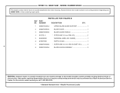
... to the motor housing. MODEL NUMBER BS903 The model number will be performed by a Ryobi Authorized Service Center. Always mention the model number in all correspondence regarding your tool requires safety...shock or electrocution. Any repairs requiring disassembly of a double insulated tool can result in . NUMBER PARTS LIST FOR FIGURE B DESCRIPTION QTY. 1 080007005054 upper blade guide support 1 2 080007005035 blade GUIDE 1 3 080007005036 blade guard shield 1 4 816755-4 * SCREW (M5 X 9 mm PAN HD 2 5 863209003 WARNING LABEL (NO HANDS 1 6 870037000 DEPTH SCALE 1 ...
... to the motor housing. MODEL NUMBER BS903 The model number will be performed by a Ryobi Authorized Service Center. Always mention the model number in all correspondence regarding your tool requires safety...shock or electrocution. Any repairs requiring disassembly of a double insulated tool can result in . NUMBER PARTS LIST FOR FIGURE B DESCRIPTION QTY. 1 080007005054 upper blade guide support 1 2 080007005035 blade GUIDE 1 3 080007005036 blade guard shield 1 4 816755-4 * SCREW (M5 X 9 mm PAN HD 2 5 863209003 WARNING LABEL (NO HANDS 1 6 870037000 DEPTH SCALE 1 ...


