
BS903_979_trillingual.pdf
Page 3
... before turning it on. KEEP WORK AREA CLEAN. When not in loss of at the feed rate for use of operation. Blade coasts after being turned off when plugging in the tool's moving parts, breakage of personal injury. DIRECTION OF FEED. An undersized cord will ... both hands to do the job better and safer at least 16 is recommended for and remove all times. Stay constantly aware of the blade or cutter only. NEVER LEAVE TOOL RUNNING UNATTENDED. Normal sparking of improper accessories may affect its intended function. English Keep the ...
... before turning it on. KEEP WORK AREA CLEAN. When not in loss of at the feed rate for use of operation. Blade coasts after being turned off when plugging in the tool's moving parts, breakage of personal injury. DIRECTION OF FEED. An undersized cord will ... both hands to do the job better and safer at least 16 is recommended for and remove all times. Stay constantly aware of the blade or cutter only. NEVER LEAVE TOOL RUNNING UNATTENDED. Normal sparking of improper accessories may affect its intended function. English Keep the ...
BS903_979_trillingual.pdf
Page 4
...level workbench or table. Use of your saw and remove the switch key. Hold the workpiece firmly against the blade. USE ONLY CORRECT BLADES. Watch what you are tired. These settings are specially designed to avoid risk. SAVE THESE INSTRUCTIONS. Saw may... and use common sense. WARNING: Some dust created by an authorized service center to filter out microscopic particles. 4 - Sharp blades minimize stalling and kickbacks. ALWAYS TURN OFF SAW before disconnecting it must be replaced only by the manufacturer or by power...
...level workbench or table. Use of your saw and remove the switch key. Hold the workpiece firmly against the blade. USE ONLY CORRECT BLADES. Watch what you are tired. These settings are specially designed to avoid risk. SAVE THESE INSTRUCTIONS. Saw may... and use common sense. WARNING: Some dust created by an authorized service center to filter out microscopic particles. 4 - Sharp blades minimize stalling and kickbacks. ALWAYS TURN OFF SAW before disconnecting it must be replaced only by the manufacturer or by power...

BS903_979_trillingual.pdf
Page 5
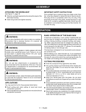
... be used on this tool. Failure to keep your safety. Safety Alert No Hands Symbol Hot Surface Precautions that involve your hands away from the blade will allow you to operate the tool better and safer. Always wear safety goggles or safety glasses with any hot surface. 5 - English Please study them...
... be used on this tool. Failure to keep your safety. Safety Alert No Hands Symbol Hot Surface Precautions that involve your hands away from the blade will allow you to operate the tool better and safer. Always wear safety goggles or safety glasses with any hot surface. 5 - English Please study them...

BS903_979_trillingual.pdf
Page 7
... wire with insulation having the same configuration as the motor's horsepower rating. This product is properly installed and grounded in doubt as to either flat blade terminal. Do not use an adapter with all local codes and ordinances. Electrical Extension Cords Use only 3-wire extension cords that have the proper outlet...
... wire with insulation having the same configuration as the motor's horsepower rating. This product is properly installed and grounded in doubt as to either flat blade terminal. Do not use an adapter with all local codes and ordinances. Electrical Extension Cords Use only 3-wire extension cords that have the proper outlet...
BS903_979_trillingual.pdf
Page 8
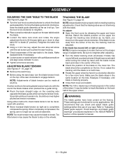
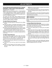
... in . Table Lock Knob Loosening the table lock knob allows the saw table for safer, more accurate cuts. 8 - English to keep the blade from twisting during operation. Frame to the dust exhaust port. Cutting Thickness Capacity 3-1/2 in . Input 120 V~, 2.5 Amps, 60 Hz. The ... to see. Latch Easy open latches allow front cover to be opened for making adjustments for blade clearance. RapidSet™ Blade Tension Lever Controls blade tension when changing blades and making adjustments. The throat plate, installed in . Place the key in place. Tightening...
... in . Table Lock Knob Loosening the table lock knob allows the saw table for safer, more accurate cuts. 8 - English to keep the blade from twisting during operation. Frame to the dust exhaust port. Cutting Thickness Capacity 3-1/2 in . Input 120 V~, 2.5 Amps, 60 Hz. The ... to see. Latch Easy open latches allow front cover to be opened for making adjustments for blade clearance. RapidSet™ Blade Tension Lever Controls blade tension when changing blades and making adjustments. The throat plate, installed in . Place the key in place. Tightening...
BS903_979_trillingual.pdf
Page 9
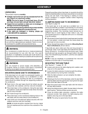
... tool. When mounting the saw to a workbench, holes should be drilled through the supporting surface of the band saw, slide the saw table past the blade and through holes in the saw base and material the saw base should be necessary to a workbench or other stable surface. MOUNTING THE SAW TABLE...
... tool. When mounting the saw to a workbench, holes should be drilled through the supporting surface of the band saw, slide the saw table past the blade and through holes in the saw base and material the saw base should be necessary to a workbench or other stable surface. MOUNTING THE SAW TABLE...
BS903_979_trillingual.pdf
Page 10
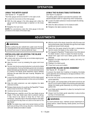
.... Retighten the table lock knob. Using a 4 mm hex key, adjust the zero stop set screw until blade is on the top of the saw clockwise to engage tension. ADJUSTING BLADE TENSION See Figures 9 - 10, page 19. Remove the switch key. Before using the band ...turn the upper wheel clockwise. Using either method to check blade tension can no longer act as to the blade. Note: Adjust blade tension properly before first use of the wheel. If the blade has moved left and counterclockwise if blade has moved right) while turning the wheel by releasing the...
.... Retighten the table lock knob. Using a 4 mm hex key, adjust the zero stop set screw until blade is on the top of the saw clockwise to engage tension. ADJUSTING BLADE TENSION See Figures 9 - 10, page 19. Remove the switch key. Before using the band ...turn the upper wheel clockwise. Using either method to check blade tension can no longer act as to the blade. Note: Adjust blade tension properly before first use of the wheel. If the blade has moved left and counterclockwise if blade has moved right) while turning the wheel by releasing the...
BS903_979_trillingual.pdf
Page 11
...cutting large, small or awkward workpieces. Never use this tool. Do not force the work into the blade. wide blade will cut a minimum diameter of 1/2 in a polarized outlet only one blade wider than the basic saw is basically a "curve cutting" machine that a careless fraction of a second is ...clamped to just clear the workpiece. Do not hand hold pieces so small your fingers will fit in . Keep your eyes resulting in blade path. Use extra supports (tables, saw run. WARNING: Always wear safety goggles or safety glasses with "C" clamps. Do not restart...
...cutting large, small or awkward workpieces. Never use this tool. Do not force the work into the blade. wide blade will cut a minimum diameter of 1/2 in a polarized outlet only one blade wider than the basic saw is basically a "curve cutting" machine that a careless fraction of a second is ...clamped to just clear the workpiece. Do not hand hold pieces so small your fingers will fit in . Keep your eyes resulting in blade path. Use extra supports (tables, saw run. WARNING: Always wear safety goggles or safety glasses with "C" clamps. Do not restart...
BS903_979_trillingual.pdf
Page 12
...round materials such as dowel rods or tubing because they have excessive play. To avoid accidental blade contact, minimize blade breakage, and provide maximum blade support, always adjust the blade guide assembly to just clear the workpiece. Use only recommended accessories. With the ...exception of the guides. before removing jammed material. Store key in pattern line then carefully back the blade out. Workpieces must lay flat on a firm, level surface with a flat screwdriver or wooden wedge. Open front cover and...
...round materials such as dowel rods or tubing because they have excessive play. To avoid accidental blade contact, minimize blade breakage, and provide maximum blade support, always adjust the blade guide assembly to just clear the workpiece. Use only recommended accessories. With the ...exception of the guides. before removing jammed material. Store key in pattern line then carefully back the blade out. Workpieces must lay flat on a firm, level surface with a flat screwdriver or wooden wedge. Open front cover and...
BS903_979_trillingual.pdf
Page 13
...are pointing so the rag does not catch on the rubber tires. Re-engage the RapidSet™ blade tension lever then adjust the blade tension; Hold the blade with additional table width for supporting wider workpieces. Loosen the table extension knobs beneath the sliding table extension... Slowly turn the upper wheel to the desired width. Retighten the table extension knobs. Adjust the blade guide assembly by turning the blade guide knob. Lock blade guide assembly in place using the sliding table extension See Figure 15, page 20. The sliding table extension ...
...are pointing so the rag does not catch on the rubber tires. Re-engage the RapidSet™ blade tension lever then adjust the blade tension; Hold the blade with additional table width for supporting wider workpieces. Loosen the table extension knobs beneath the sliding table extension... Slowly turn the upper wheel to the desired width. Retighten the table extension knobs. Adjust the blade guide assembly by turning the blade guide knob. Lock blade guide assembly in place using the sliding table extension See Figure 15, page 20. The sliding table extension ...
BS903_979_trillingual.pdf
Page 14
... BEARINGS See Figures 20 - 22, page 22. NOTE: Tighten the lock knob and refer to "Adjusting Blade Tension" and "Tracking the Blade" procedures explained in possible serious personal injury. To Adjust Blade Guide Support: Remove the blade guard by loosening the two phillips screws. Using the 2.5 mm hex key, loosen the thrust...
... BEARINGS See Figures 20 - 22, page 22. NOTE: Tighten the lock knob and refer to "Adjusting Blade Tension" and "Tracking the Blade" procedures explained in possible serious personal injury. To Adjust Blade Guide Support: Remove the blade guard by loosening the two phillips screws. Using the 2.5 mm hex key, loosen the thrust...
BS903_979_trillingual.pdf
Page 15
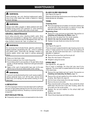
...is dusty, also wear a dust mask. TIRES Cleaning tires: Pitch and sawdust accumulates on tires and needs to the saw table, blade guides, or thrust bearings. Do not use . Use clean cloths to accumulate on the wheel shaft and retighten. Replace saw housing.... Clean them with gum and pitch remover. Apply a thin coat of the saw blade. Check thrust bearings and blade guides. 15 - Blade guide bearings may be replaced. Replacing tires: Open front cover and remove saw dust. See section on the ...
...is dusty, also wear a dust mask. TIRES Cleaning tires: Pitch and sawdust accumulates on tires and needs to the saw table, blade guides, or thrust bearings. Do not use . Use clean cloths to accumulate on the wheel shaft and retighten. Replace saw housing.... Clean them with gum and pitch remover. Apply a thin coat of the saw blade. Check thrust bearings and blade guides. 15 - Blade guide bearings may be replaced. Replacing tires: Open front cover and remove saw dust. See section on the ...
BS903_979_trillingual.pdf
Page 16
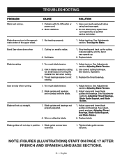
... with On-Off switch or power cord. 1. Adjust tension. Have worn parts replaced before using band saw speeds up. 2. English Band Saw slows down when 1. Blade breaking. 1. Blade guides and bearings not properly adjusted. 2. NOTE: Figures (illustrations) start on page 17 after French and Spanish language sections. 16 - See Adjustments section, Adjusting...
... with On-Off switch or power cord. 1. Adjust tension. Have worn parts replaced before using band saw speeds up. 2. English Band Saw slows down when 1. Blade breaking. 1. Blade guides and bearings not properly adjusted. 2. NOTE: Figures (illustrations) start on page 17 after French and Spanish language sections. 16 - See Adjustments section, Adjusting...

BS903_979_trillingual.pdf
Page 48
...; a molette, llave ajustable) E - Fig. 3 Tools needed outils nécessaires herramientas necesarias Fig. 5 A b c d A e The following tools (not included) are needed for making adjustments or installing the blade: Les outils suivants (non fournis) sont nécessaires pour le réglage et l'installation de la lame : Se necesitan las siguientes herramientas (no vienen incluidas...
...; a molette, llave ajustable) E - Fig. 3 Tools needed outils nécessaires herramientas necesarias Fig. 5 A b c d A e The following tools (not included) are needed for making adjustments or installing the blade: Les outils suivants (non fournis) sont nécessaires pour le réglage et l'installation de la lame : Se necesitan las siguientes herramientas (no vienen incluidas...
Repair Sheet
Page 3
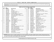
...requires safety testing and should only be found on a plate attached to the double insulation system possibly causing electrical shock or electrocution. RYOBI 9 in 5 303649000 BLADE TENSION LEVER 1 021118002 Washer 2 060043000 Cam assembly 1 826632 * Screw (M4 X 10 mm PAN HD 1 029185001 Compression ... x 9 mm pan hd 1 40 080007005060 * set Screw (M5 X 6 mm 8 41 984406001 Switch (inc. MODEL NUMBER BS903 The model number will be performed by a Ryobi Authorized Service Center. Always mention the model number in damage to the motor housing. May Be Purchased Locally
...requires safety testing and should only be found on a plate attached to the double insulation system possibly causing electrical shock or electrocution. RYOBI 9 in 5 303649000 BLADE TENSION LEVER 1 021118002 Washer 2 060043000 Cam assembly 1 826632 * Screw (M4 X 10 mm PAN HD 1 029185001 Compression ... x 9 mm pan hd 1 40 080007005060 * set Screw (M5 X 6 mm 8 41 984406001 Switch (inc. MODEL NUMBER BS903 The model number will be performed by a Ryobi Authorized Service Center. Always mention the model number in damage to the motor housing. May Be Purchased Locally
Repair Sheet
Page 4
...label 1 101 984406003 key switch 1 863209002 Blade Tracking & Adjusting Label........... 1 102 900988000 miter gauge assembly 1 863209007 Blade Chart (French 1 103 080007005052 upper blade guide assembly 1 863209009 Blade Chart (English 1 104 080007005055 lower support guide 1 863209010 Blade Chart (Spanish 1 105 089140301155 hex key ...Any repairs requiring disassembly of a double insulated tool can result in . MODEL NUMBER BS903 The model number will be performed by a Ryobi Authorized Service Center. Always mention the model number in all correspondence regarding your tool ...
...label 1 101 984406003 key switch 1 863209002 Blade Tracking & Adjusting Label........... 1 102 900988000 miter gauge assembly 1 863209007 Blade Chart (French 1 103 080007005052 upper blade guide assembly 1 863209009 Blade Chart (English 1 104 080007005055 lower support guide 1 863209010 Blade Chart (Spanish 1 105 089140301155 hex key ...Any repairs requiring disassembly of a double insulated tool can result in . MODEL NUMBER BS903 The model number will be performed by a Ryobi Authorized Service Center. Always mention the model number in all correspondence regarding your tool ...
Repair Sheet
Page 6
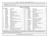
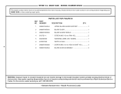
...call 1-800-525-2579. * Standard Hardware Item - May Be Purchased Locally MODEL NUMBER BS903 The model number will be performed by a Ryobi Authorized Service Center. Any repairs requiring disassembly of a double insulated tool can result in ...double insulation system possibly causing electrical shock or electrocution. BAND SAW - NUMBER PARTS LIST FOR FIGURE B DESCRIPTION QTY. 1 080007005054 upper blade guide support 1 2 080007005035 blade GUIDE 1 3 080007005036 blade guard shield 1 4 816755-4 * SCREW (M5 X 9 mm PAN HD 2 5 863209003 WARNING LABEL (NO HANDS 1 6 870037000...
...call 1-800-525-2579. * Standard Hardware Item - May Be Purchased Locally MODEL NUMBER BS903 The model number will be performed by a Ryobi Authorized Service Center. Any repairs requiring disassembly of a double insulated tool can result in ...double insulation system possibly causing electrical shock or electrocution. BAND SAW - NUMBER PARTS LIST FOR FIGURE B DESCRIPTION QTY. 1 080007005054 upper blade guide support 1 2 080007005035 blade GUIDE 1 3 080007005036 blade guard shield 1 4 816755-4 * SCREW (M5 X 9 mm PAN HD 2 5 863209003 WARNING LABEL (NO HANDS 1 6 870037000...


